Continue to Site

Eng-Tips is the largest engineering community on the Internet

Intelligent Work Forums for Engineering Professionals

  • Congratulations KootK on being selected by the Eng-Tips community for having the most helpful posts in the forums last week. Way to Go!

Joint design of a post and beam associated with a knee brace.

Status
Not open for further replies.

Weaverofduart

Agricultural
Nov 5, 2010
28
Knees braces are used to prevent a post and beam frame from wracking under lateral loads. Everyone knows that.

But just adding knee braces where ever isn't a solution. The size of the knee brace (as in its length) makes a big difference.

The longer the knee brace the more it protrudes into the usable space of the timber frame but the smaller the knee brace the stronger the joint between the associated post and beam has to be.

When a frame is laterally loaded the leeward (down wind) knee brace will be under compression. Timber is generally very good under compression so even a moderately sized knee brace will be more than adequate.

This means that the most likely point of failure is the mortice and tenon joint between the associated post and beam which will be under tension.

The shorter the knee brace the greater the leverage against this joint.

How do I calculate the horizontal and vertical reaction forces in this joint so that I can appropriately determine the length/positioning of the knee brace (compromise of usability of internal space versus strength), the size of the tenon and the required relish of the wood surrounding the mortice.
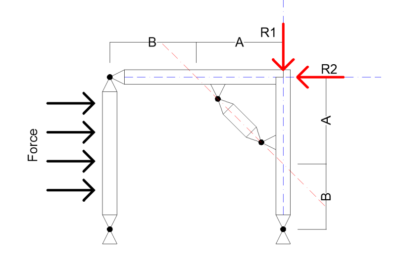
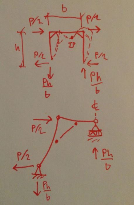
Braced_Frame_Diagram_mehpku.png


I've drawn this diagram to emphasise the key roll of the post and beam joint on leeward side of the frame. Assuming that all the other joints are working as hinges that means that this joint has to be able to deal with all the reaction forces by itself.
 
Replies continue below

Recommended for you

Not sure how you plan on modeling the mortise and tenon joint, but I would model it as pinned. A moment connection in wood can be very challenging to design and construct. Also, all of the joints will resist some portion of the load. The mortise and tenon joint does not resist 100% of the load just because all of the other joints are hinged. Lastly, you have your analysis procedure backwards.....you must first locate the brace and then determine the forces at the connection. You cannot determine the forces without knowing the brace location. If the resulting forces are undesirable, simply adjust the brace location. This frame analysis is easily accomplished with most software on the market (Staad, Risa, Ram, etc)....or if you are feeling structurally savvy, try doing it by hand. You don't mention what this structure is, but you will most likely need to consider the resulting sway/drift of this frame which will be influenced by brace size and location.
 
I've found in general wood knee braced frames are controlled by the capacity of the connection between the knee brace and the beam / column. Obviously, you need to run through all the other checks but I'd do that one first as it can be tricky to make that connection work. I'd model all joints as pinned.
 
@jdgengineer

I'm surprised that you would say that the limiting capacity is that between the knee brace and the post.

I guess it would depend on the joint. If it were a beam tennoned into a post then that could makes sense. I still would have thought that the tenon or the peg/s would have been the week point.

The joint I'm working on is an English tieing joint. Therefore I expect the weak point is going to be the tenon going through the beam.

@Motorcity

Yes all the joints will resist some of the load but its conservative to assume they don't.

Locating the brace/designing the joint will take a bit iteration but I was stumped by the method.

I'm not a structural engineer so I don't have the professional software. Normally I'm designing pipe networks and water treatment systems.

The structure is actually a range of different timber frame structures. I've got the option on several truckloads of wood and I want to get an idea of what we can do with the relatively small diameter logs.
 
Got this sorted Weaver? If not, I've got some stuff to add.

I like to debate structural engineering theory -- a lot. If I challenge you on something, know that I'm doing so because I respect your opinion enough to either change it or adopt it.
 
I think that you can:

1) Treat the knee-braced frame as a permutation of an ordinary moment frame in many respects.

2) Assume a point of inflection at the center of the beam for lateral load.

3) Work out your forces based on the resulting, statically determinate, half model shown below.

4) Add the results from your lateral load case to your other load cases as appropriate.

Font_wr8gw6.jpg


I like to debate structural engineering theory -- a lot. If I challenge you on something, know that I'm doing so because I respect your opinion enough to either change it or adopt it.
 
Bearing in mind I'm still self teaching (as distinct from taught) structural engineer....

Timber framing manuals produced by the Timber Framing Guild recommend to ignore the effect of braces under tension.

So I don't think you can assume the point of inflection is centered in the beam. Rather I would say the point of inflection is at the knee brace.

So I'll outline my thoughts and see if my reasoning is ok.

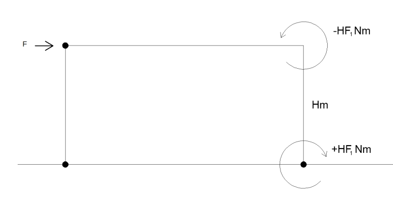
Simplifying the diagram....

The load wants to cause the posts to tip over. So there must be a moment about the hinge at the bottom of the posts. Considering the right post this moment would equal the load (F) by the length of post (H). Since the frame is in equilibrium there must be an opposite moment at the top of the post. The only place within the frame that is resisting the load in a way to prevent the frame collapsing is the joint at the top of the right post.

The moment at the top of the right post must be being formed by a force drawn from the beam. If this joint is rigid and the joint at the top of the LEFT post broke then we would expect the rigid frame of the right post and beam to rotate as a unit.
brace_1_c7nkaj.png

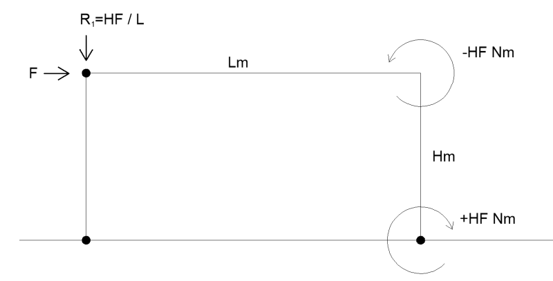
Since this isn't happening there must be a downward force within that hinge joint formed by the top of the left post and left end of the beam.
brace_2_fx3r0w.png

Having found this reaction force I added the brace back into the diagram. Here we see that the placement of the brace can massively effect the force on the right post/beam connection. The smaller the brace the greater the leverage on the joint.
brace_3_u0xrys.png

Calculated the forces on the beam by treating it as balanced about the top of the brace. Which gives the vertical reaction (R2) at the top of the post.
brace_4_fvfjw8.png

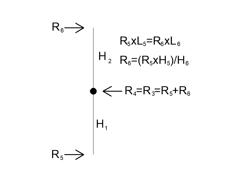
To get the horizontal reaction and presuming the brace is at 45 degrees the lateral load on the post (R4) is equal to R3. That allows me to calculate the lateral load at the top of the post (R6).
Brace_5_m5g5k4.png


So how did I do?
 
isn't the structure the the right of the pinned column a two force member ?

doesn't that mean that the frame is putting the column in tension.

You can draw a FBD of the overall structure to see where the off-set couple comes out.

another day in paradise, or is paradise one day closer ?
 
OP said:
Timber framing manuals produced by the Timber Framing Guild recommend to ignore the effect of braces under tension.

Didn't know that. Can you point me to a document that I can review?

OP said:
So I don't think you can assume the point of inflection is centered in the beam. Rather I would say the point of inflection is at the knee brace.

It wouldn't be at the mid-point or anywhere else in the beam. You'd no longer have any inflection points anywhere in the system with the bases pinned.

OP said:
So how did I do?

I wouldn't consider the column base to be moment fixed. The system is stable without that anyhow.

I like to debate structural engineering theory -- a lot. If I challenge you on something, know that I'm doing so because I respect your opinion enough to either change it or adopt it.
 
I've got a bunch of the publications from the TFG but the most relevant two are:


"It wouldn't be at the mid-point or anywhere else in the beam. You'd no longer have any inflection points anywhere in the system with the bases pinned."

Probably shouldn't have used the word "inflection". There would be deflection about the brace.

Is the approach I've used wrong? Good enough?

My normal work as an agricultural engineer is more to do with designing pipe networks, water processing installations and climate control. Structural engineering is something I've been teaching myself for fun.

Engineers that are willing to certify designs that only use wood are pretty rare here in Australia. Everyone I've talked to so far has wanted to add steel at all joints under tension. So my aim is to learn enough to be able to rough out the design and do the bulk of the iterations. Then hand it over to a professional to finish and certify. If I have to get a professional to do all the design work it will cost me a fortune.

Plus I love learning.
 
I'd've thought the overall FBD would look like ...
Untitled_g6evdu.png


another day in paradise, or is paradise one day closer ?
 
Status
Not open for further replies.

Part and Inventory Search

Sponsor