Eng-Tips is the largest engineering community on the Internet

Intelligent Work Forums for Engineering Professionals

  • Congratulations waross on being selected by the Eng-Tips community for having the most helpful posts in the forums last week. Way to Go!

Joints in Concrete Framed Stair

Status
Not open for further replies.

bbookz

Structural
Oct 19, 2005
27
US
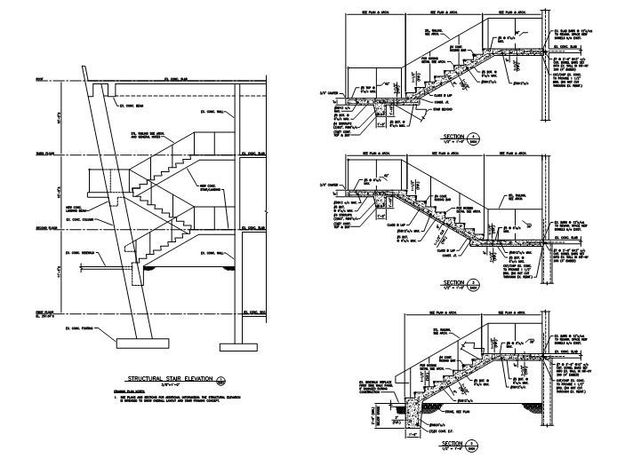
I'm working on a concrete framed stair. It is open on the exterior long side, so I've designed the stair to span the long direction between the exterior wall of the building and an intermediate landing beam (stringer and landings together make up the span). I know there are going to be construction joints and am planning calling for the stair to be poured in (3) L's with all three landings being pour continuous each integral with one of the connecting stringers.

Another engineer in my office liked the idea of the stringer to landing joints being horizontal so that the stringer sits on top of the landings below (see attached PDF). What kind of gets away from me in this detail is what to do with the shear. If the cold joint were vertical right where the stringer meets the landing I could easily comprehend what to do with the shear and design for shear-friction transfer. It looks better to me as a horizontal joint and their is more contact between surfaces, but I don't really know how to design the shear interface (Its kind of like having a horizontal joint in a beam). I think their may be a way to analyze this condition by transposing forces at angles, but this seems like a common condition so I'd like to get a consensus on best method for detailing/designing/locating the joint.

As a side note, the stair is replacing an existing semi-exposed exterior stair at the corner of a building that has aged/deteriorated to the point that it's a constant maintenance concern (Its 46 years old). I plan on using 4.5 ksi mix, 1-1/2 cover and penetrating sealer to mitigate corrosion/moisture damage.
 
Replies continue below

Recommended for you

What happens if you idealize this connection as a roller?
 
I don't see the referenced PDF file. Sometimes the system objects to file names with spaces.

So I don't have a clear picture of what is going on. I'm guessing that your stair stringers are upturned and form some part of the guard rail system. Like a bucket within which people walk. I'm also speculating that the intermediate landings cantilever off of the building somehow and support your stringers intermittently. If that's true than you should be fine and your shear issues would be:

1) horizontal interface shear for the stringer hogging moment at the landing if the landing concrete needs to be part of the stringer flexural compression block.

2) one way vertical shear checks and detailing in the landing slab or beams that cantilever out to pick up the stringers.

I like to debate structural engineering theory -- a lot. If I challenge you on something, know that I'm doing so because I respect your opinion enough to either change it or adopt it.
 
I've re-uploaded the stair file as a jpeg. No, the stair looks like a standard stair - when I say stringers I just mean the angled tread run as opposed to the horizontal landing (there are no upturned stringer beams). I'm designing the landing and treads to span together as a one way slab. The landings are supported by a wall on the building side and by a beam spanning between columns on the intermediate landing side. Supports are Pinned-Pinned with a cantilever slab at the intermediate landing beam. Each landing is poured with one tread run per the attached highlighted plan. The joint will have top and bottom bars with class B lap lengths on each side, so that bending tension is taken care of. The bending compression and shear would have to be resisted by dowels at the joint. I'm open to alternate joint locations/orientations. My initial inclination was to have a vertical construction joint at the tread run/landing interface since its easier for me to understand - i.e. continue bottom steel through the joint for the moment and roughen vertical plane and have additional shear dowels to handle the shear. A coworker liked the horizontal joint layout since it allows for more contact between the landing and stair run, also probably allows less water into the joint, and just seems logical to bear the stair run on the landing from a constructibility standpoint.

Capture_gqgluy.jpg


Plan_vuuzvl.jpg
 
Got it, thanks. The geometry of the concrete suggests the common situation where the stringer slab bears on the landing slab as a pinned joint which, as you've stated, is not your intention. With the right rebar detailing, you could achieve the continuity that you need but you'll have a bit of an awkward first pour situation with bars sticking out of the top at weird angles. It can certainly be done but my preference would be for a vertical joint as you originally proposed. Aesthetics may favour the horizontal joint as it would be hidden from view.

As for shear with the horizontal joint, that is a tricky thing. I've not seen that specifically considered before in practice. I suspect that it's not a big deal as most of the vertical shear should get transferred across the joint in direct bearing. To look at it in detai, you'd probably want to investigate it as a closing concrete joint and employ a method like strut and tie. Of course, nobody's got that kind of time to spend in a stair unless it's a matter of personal academic interest. Often with stairs, the geometry is such that it's tough to even tell whether the joint is opening or closing under load. Detailing often covers both conditions, at least nominally, to be safe.

I like to debate structural engineering theory -- a lot. If I challenge you on something, know that I'm doing so because I respect your opinion enough to either change it or adopt it.
 
You haven't mentioned anything about that sloping column. How are you handling the horizontal forces on the column?

BA
 
Status
Not open for further replies.

Part and Inventory Search

Sponsor

Back
Top