Continue to Site

Eng-Tips is the largest engineering community on the Internet

Intelligent Work Forums for Engineering Professionals

  • Congratulations KootK on being selected by the Eng-Tips community for having the most helpful posts in the forums last week. Way to Go!

Joist Dimensions Assistance 1

Status
Not open for further replies.

IanVG

Mechanical
Jan 21, 2022
74
Hello all,

Just a warning, I come from the mechanical engineering side, so please forgive my ignorance. I am creating a Revit model for a project involving a lot of tight tolerances for ductwork. After the ceiling was torn out, I was in discussion with the contractors to see where and how the ductwork was going to fit in. We discussed using the volume within the span of the concrete joist framing above the ceiling to route some parts of the ductwork.

The model isn't strictly necessary and I don't need it for any kind of structural analysis, just ductwork clearance. Okay, that being said, I have access to the structural drawings, which date form 1961, so they are bit difficult to decipher. I think I figured the span direction and which parts of the framing consists of which kind of joists. There's also a joist schedule at the end that spells out the spec's for the joists. Problem is, I have no idea what it is trying to communicate. No structural engineers are in my office just mechanical and electrical, and they are not interested in this question.

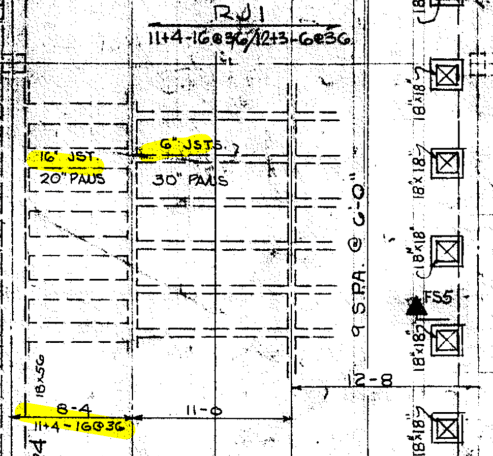
For joist RJ1, what does 11+4, 16@36/12+3, 6@36 mean? I think that 36 refers to the span between the beams (i.e. 36"). And I think maybe that the 11+4 and the 12+3 refers to span length (so maybe 11'-4" and 12'-3"?).

I am attaching a snippet of the part of the structure I am trying to model and a link to the joist schedule because I don't know which part of the schedule is relevant. Any help is greatly appreciated!

Framing_excerpt_udcozn.png
 
Replies continue below

Recommended for you

I've never read pan joist drawings like this before, so maybe someone else can give you better information. This is how I interpret it.

I think the numbers are pan depth, slab depth, width of joist @ spacing. So the 11+4-16@36 is an 11" joist below a 4" slab (15" total depth), with a 16" width @ 36" o.c. The 12+3-6@36 is a 12" joist below a 3" slab (15" total depth), with a 6" width at 36" o.c.

Go Bucks!
 
Thanks @straub46 for the info. That makes sense from my site-visit and the plans. Is there a source (text, internet, otherwise) that would help interpret structural plans and annotations from the 1950's to the 1970's? I appreciate the help, but, haha, I have a few more questions.
 
Actually I'll go ahead and ask it, the schedule for the beams specifies that the RB25 is "30 x 15", does that mean the beam is 30" wide and has a depth of 15"? And does this imply that the beam top height is the same as the slab? Or was the slab poured using some kind of form over the beam? I hope these questions make sense.

Edit: Haha, I'm going to complete this udemy course and maybe I won't be so completely lost. If there is a book or other 'crash course' lesson out there that someone could recommend that would super appreciated!
 
You should also take a look at the typical details on the 2nd page of your drawings. It shows the slab cast integral with the beams and joists. Based off how it's drawn and that detail, I would think it's 30" wide x 15" total depth.

Go Bucks!
 
Hmm, I saw that detail but I wasn't sure if it was implied that the slab was to be poured on top of that. Thanks again. And just to go back to the original question, how do I know if the joist is a 11+4-16@36 or a 12+3-6@36? There may be detail or comment in there that's obvious to a structural engineer, but I'm not seeing anything.

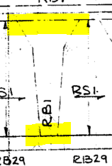
Edit: Same question applies for beams. If the schedule says that beam RB14 is 36/48x15, what does the 36/48 mean?
 
The plan view shows what they look like and where they extend.

Capture_vnkl97.png


Probably that it transitions in width. Take a look at what the plans show.

Capture2_d7y1ok.png


Go Bucks!
 
I think the pans tended to be either 20” or 30”. So a 4” wide joist rib with a 20” pan was 24” c/c on the joists. Joists usually have shear issues so 30” wide pans needed 6” min widths to get the shear capacity (and worked out to a nice 36” on center).
 
And often when they reference something like 36/48 it usually means for part of the beam it is 36" wide and another part of it is 48". Likely next to an opening or something along those lines.

If I'm understanding correctly you want to use some of the spaces between the joists to run mechanical. I don't believe I've seen anyone warn you about the full depth bridging at about mid-span of the joists that would prevent the mechanical from running the entire length of the joist inside the joist space. Just a caution.
 
Thank you everyone for their insight! I feel like I finally made progress on understanding and modeling better as-builts for my drawings. I was even able to verify the accuracy of my model with a laser scan, and it wasn't too bad!

I am working on another building with similarly older drawings and I had a question about beam locations. I figure I'd use this post to ask (not too frequently!) questions about this subject (also in the hope that future engineers/modelers may benefit from this discourse).

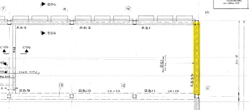
Basically, my question is do these drawings indicate where the edge of the beam is located clearly? Or typically, would you expect a detail somewhere to outline this piece of information?

Beam_locations_1_fr9plu.jpg
Beam_schedule_1_mxdap1.jpg


I am attaching a screenshot of the plan drawing and the beam referenced on the plan. In addition, would a detail be needed to understand how many inches off center (o.c.) the first joist would run from RB-35? I would assume 36", but I'm not sure if that's from the center of RB-35 or the edge of it.
 
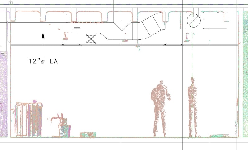
Also, I am coming back to this thread to note that after completing a laser scan of the room I am doing a renovation in, I found a consistent difference in 4" between what I expected the drawings to be and reality. In other words, the structure is lower by 4" than I expected. Is there any possible reason for why this happened? I am attaching a snippet of what I mean.

Finished_floor_height_differences_iahfa2.jpg
 
Sometimes in these old buildings you have a terrazzo or thick set tile floor, the top of which is at "finish floor". This would lower the structural floor accordingly.
 
Status
Not open for further replies.

Part and Inventory Search

Sponsor