Continue to Site

Eng-Tips is the largest engineering community on the Internet

Intelligent Work Forums for Engineering Professionals

  • Congratulations KootK on being selected by the Eng-Tips community for having the most helpful posts in the forums last week. Way to Go!

L-shaped Retaining Wall (no toe) and "J"-shaped retaining wall (no heel) joint detailing

Status
Not open for further replies.

msdmoney

Structural
Sep 13, 2006
19
I've been working through some retaining wall details for a project that requires a condition with a footing without a toe and a footing without a heel. I'm curious on how others detail the wall to footing joint.

For a T-shaped footing, I typically detail per the CRSI manual, developing the toe bars and extending up into the stem. I will often omit the diagonal for shorter walls. If the toe is too short to fully develop, I hook the "O" bar.
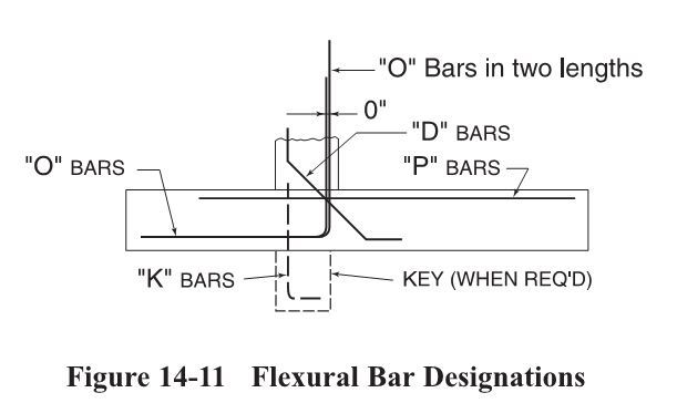
Retaining_wall_footing_vmmwgh.jpg


For the L-shaped footing, when there is no toe and only one curtain of reinforcing in the stem, I'm looking at the best way to detail to fully develop the joint moment at the corner.The "O" bars would need to turn the other direction into the bottom of the heel in order to develop. Since the heel bars can't develop into a toe, my inclination is to turn them upward and develop into the wall.

I've been looking at some of the plan corner detailing conditions shown in Concrete International's detailing corner.
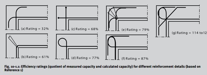
Wall_Corner_details_tms2tv.jpg
 
Replies continue below

Recommended for you

1) For serious toeless walls, I'll do something like G but using U-bars lapped with the flexural bars.

2) For minor toeless walls, I'll do the same as #1 but, instead of the diagonal bars, I'll bump the flexural bar up 15% more than required.

3) For heel-less walls, I'll check the lapped starter dowel in the corner using a curved bar node strut and tie model. For larger bars, this sometimes requires using a non-standard bend radius.


I like to debate structural engineering theory -- a lot. If I challenge you on something, know that I'm doing so because I respect your opinion enough to either change it or adopt it.
 
Toeless systems also have a rather serious stem to footing shear delivery problem that is not addressed by the joint flexural efficiency ratings. For that reason, the use of small diameter U-bars and/or the D bars is important.

I like to debate structural engineering theory -- a lot. If I challenge you on something, know that I'm doing so because I respect your opinion enough to either change it or adopt it.
 
I am still relatively new to the design world and had a few questions:

Am I required by code to check that joint is adequate for the design moment? Is this something I should be doing on top of code checks? (I am in the US so my code is ACI).

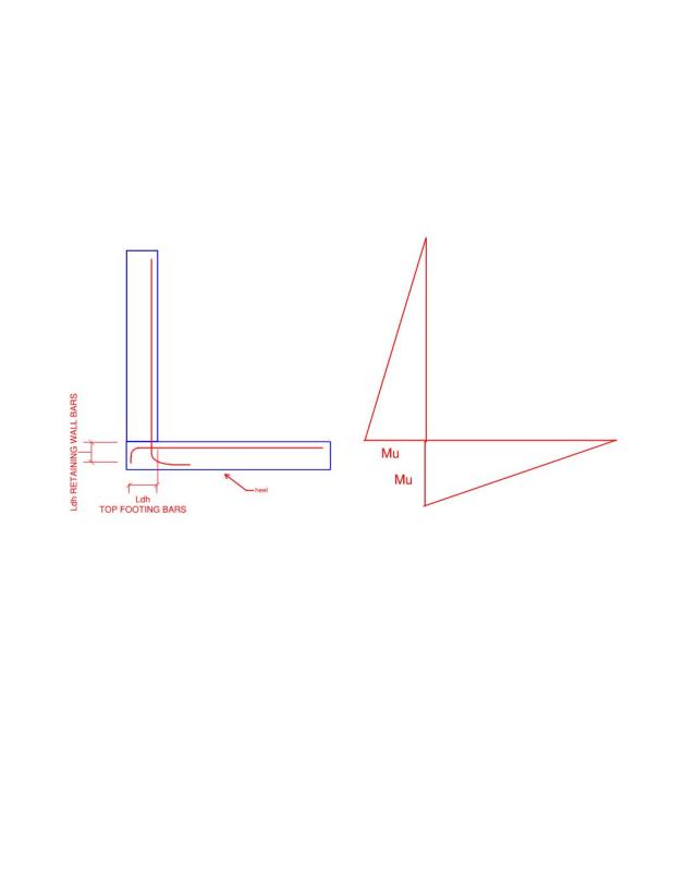
If I were to design a toeless footing here is what I would check and be done with it.

Picture_nvxd9m.jpg

I would make sure the depth of the footing allowed for ldh of the ratining wall bars and the the wall was wide enough to develop ldh of the top footing bars. Maybe this is gross ignorance?

Thanks,
S&T
 
KootK said:
Toeless systems also have a rather serious stem to footing shear delivery problem that is not addressed by the joint flexural efficiency ratings

Koot, I was also interested in your statement about shear.

Are you talking about shear friction at the joint, typical beam shear?

Does meeting the provisions for shear friction not adequately address the situation in a toeless footing?

Thanks in advance.
 
SNT said:
Am I required by code to check that joint is adequate for the design moment?

- Just like a steel joint, a concrete joint's adequacy can't be definitively guaranteed unless it has been explicitly designed.

- Industry practice has evolved to be such that designers almost never design concrete joints. For most non-lateral load resisting joints, the capacity we get from the joint simply being monolithic seems to provide adequate performance. I feel that this has lulled us into a state of complacency with respect to concrete joints and is resulting in our failing to recognize the importance of designing certain joints. I consider the toe-less retaining wall joint to absolutely be one of the joints requiring attention.

- I feel that your development length approach will generally lead to good proportions and a high probability of a successful joint. That said, development length alone is insufficient to prove a joint's adequacy. Really, development length eliminates only a single failure mode: the bars pulling out of the concrete in a bond stress-ish pullout failure. Development does not guarantee that a local chunk of concrete will not pull away from the larger mass. It also does not guarantee that there isn't an overworked compression strut in the system that will crush.

- This is an excellent and recent discussion on this very topic that you may find valuable.

- In practice, my experience has been that most designers either do not design the connection at all or design it as you've proposed with one exception: you've got the hook on your stem bars facing very much the wrong way. Anticipated compression struts should always come into the concave side of hooks.

SNT said:
Is this something I should be doing on top of code checks?

It's also a misconception that there are no ACI code checks to be performed. Many of the checks just aren't presented in 318. Instead, they reside here and here among other places.

SNT said:
Does meeting the provisions for shear friction not adequately address the situation in a toeless footing?

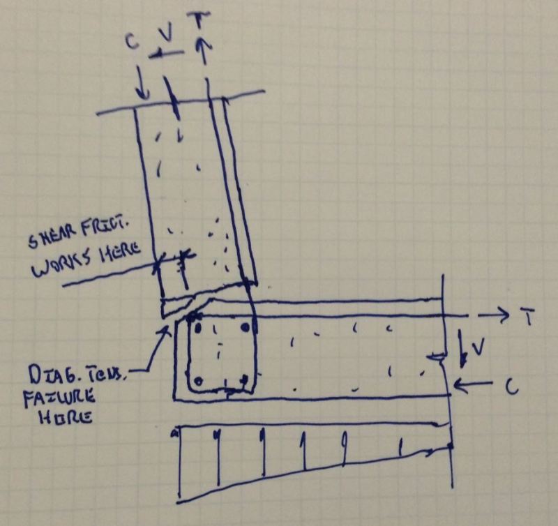
No, not in my opinion. They key to this, I believe, is to recognize that wherever you might check shear friction, there is also a complementary diagonal tension failure mode that needs to be prevented. Take a look at the sketch below and let me know if the issue doesn't pop out at you when considered this way. With toe-less retaining wall connections, it's especially bad because the flexural bars tend to be quite large and when the real world geometries of their bends are considered, you often find that no rebar crosses into that little wedge of concrete that wants to pull away.

Lean_1_tnwu1k.jpg


I like to debate structural engineering theory -- a lot. If I challenge you on something, know that I'm doing so because I respect your opinion enough to either change it or adopt it.
 

Thanks again for the input Koot, it truly is appreciated.

The diagonal tension failure due to shear friction does seem to make sense for the toeless footing.
Do you have any suggested detail to deal with this potential failure plane, some additional feel good bars?

I am also a little confused by your dimension string "shear friction works here" over a small extent of the joint. Are you implying that shear friction only works where the compression block is located? Whenever I designed for shear friction I always assumed that shear friction worked full length of the plane (full width of wall) and that the bars prevented slip past the concrete joint that enabled a region carrying tension to also resist shear.

Also, I guess I do not see how the diagonal tension failure plane would apply in a regular retaining wall foundation with a toe though. I'm going to have to think about it.


SNT said:
Thanks again for the input Koot, it truly is appreciated.

You're welcome. It's fun to discuss interesting things with inquisitive folks who care about them.

SNT said:
Do you have any suggested detail to deal with this potential failure plane, some additional feel good bars?

Yes. As I mentioned above, I'll take one of two routes:

1) If the scale of the wall is such that the rebar can be #5 or smaller, I'll make it # 5 or smaller and not worry about it. I do this in combination with longitudinal bars in the bends of the flexural rebar. We seem willing to count on this as development for beam stirrups so I feel okay about it here.

2) For larger scale walls, I include the diagonal "D" bars as shown in the CRSI manuals and discussed in the other thread.

SNT said:
Are you implying that shear friction only works where the compression block is located?

Precisely. The reason that you can double dip with your flexural tension and shear friction reinforcing is that, under flexure, the balancing compression in the compression block effectively becomes the shear friction area. This is especially true in a situation like this one where the shear friction joint is a cold joint that is effectively pre-cracked and not particularly rough. Regardless of the code provisions, it seems self evident that the lions share of the shear transfer can be expected to take place where internal compression resides.

SNT said:
..and that the bars prevented slip past the concrete joint that enabled a region carrying tension to also resist shear.

There is some of this. ACI discusses several mechanisms of shear friction and, for the case of smooth surfaces, they mention dowel action. I think that's pretty sketchy. If you imagined dowel action here, it would tend to spall the dirt side stem concrete just above the joint.

SNT said:
Also, I guess I do not see how the diagonal tension failure plane would apply in a regular retaining wall foundation with a toe though.

It wouldn't. That same shear would instead get dragged into the footing top bars and back across the heel to ultimately be resisted via friction at the soil/footing interface (depending on how you elect to resist shear in your retaining walls).


I like to debate structural engineering theory -- a lot. If I challenge you on something, know that I'm doing so because I respect your opinion enough to either change it or adopt it.
 
Oh, and my favorite way to deal with a toe-less retaining wall by far is to give the damn thing a toe. Even an extra foot does wonders to improve the joint. Also gives builders something upon which to stand the formwork.

I like to debate structural engineering theory -- a lot. If I challenge you on something, know that I'm doing so because I respect your opinion enough to either change it or adopt it.
 
Got it, thanks Koot.

I thought from your above posts that this tension failure plane existed in all cases where shear friction would be developing. I am glad I was confused then.

One other item I completely glazed over in your post from before
KootK said:
design it as you've proposed with one exception: you've got the hook on your stem bars facing very much the wrong way. Anticipated compression struts should always come into the concave side of hooks.

Do you have any reading on this? I have never heard of this before. I can't quite think of anything logical either that would make a strut better running into the concave side of a hook.
 
SNT said:
Do you have any reading on this? I have never heard of this before.

Oddly, I can't think of anything "official" that might sate your appetite for definitive reading. No codes, no hot-shot academic text books... What I can produce is a snippet from the design guideline of a well regarded concrete design firm. It's been so long since I've looked at this that I'd forgotten that it actually covers your very case.

SNT said:
I can't quite think of anything logical either that would make a strut better running into the concave side of a hook.

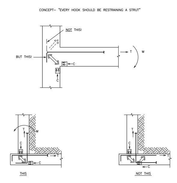
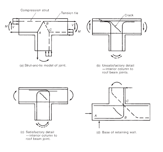
If you imagine the stresses that will develop along a hook developed bar in tension, you will come to the conclusion that there is a compression field (strut) emanating out from the concave side of the hook. As illustrated in the sketches below, you can either:

1) Have the hook direct that compression to a strut and/or tie restrained node that can resist it or;
2) Have the hook direct that compression off into no-man's land where you're counting on concrete in tension (anchorage type stuff) to keep the compression strut from blowing out.

I'm sure that you'll agree that #1 is much better even if it is not explicitly code mandated.

This_But_Not_This_ttmldg.jpg


I like to debate structural engineering theory -- a lot. If I challenge you on something, know that I'm doing so because I respect your opinion enough to either change it or adopt it.
 
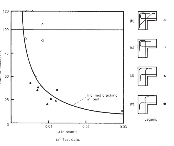
The Wight and MacGregor concrete book gives a really good explanation on the direction of hooks in chapter 17, Section 17-12, not directly in regards to retaining wall, but with regard to Beam-Column Joints. It goes into opening and closing corner joints, and (it does reference retaining walls in the t-joints) and shows the efficiency of each joint type. I came across it after posting the initial thread topic, it gave a really good breakdown of each joint condition along with an accompanying strut and tie representation that mimics what Kootk shows above. It also shows tested efficiency of each joint type. It explicitly references the turning of the dowels inward vs outward pointing dowels at a t-joint and the diagonal crack that develops. The results for turning the dowels outward away from the compression node, not good.
 
Here are some snippets from the work that msdmoney kindly referenced.

Capture14_yolcs8.png


Capture15_g8ib3p.png


I like to debate structural engineering theory -- a lot. If I challenge you on something, know that I'm doing so because I respect your opinion enough to either change it or adopt it.
 
Status
Not open for further replies.

Part and Inventory Search

Sponsor