Eng-Tips is the largest engineering community on the Internet

Intelligent Work Forums for Engineering Professionals

Laminate plate buckling analysis with Femap NX Nastran

Status
Not open for further replies.

Bruna_Mara

New member
Feb 11, 2020
5
0
0
BR
Hello!
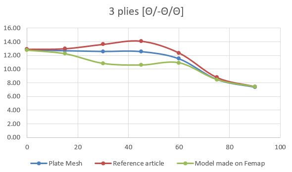
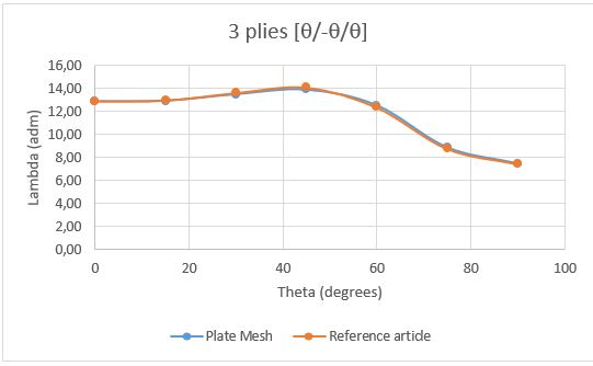
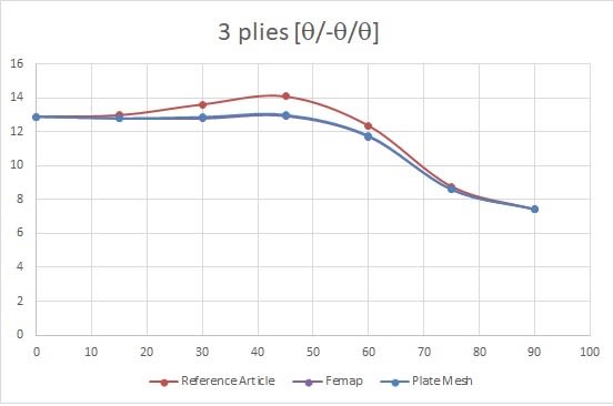
I'm an engineering student and I’m trying to learn about laminate plate buckling with FEM analysis, so I did the finite element model and used the linear bifurcation analysis (linear buckling - LBA), but the results are not as expected, according to the reference article that I was following.
The analysis was made for different fiber angle in each ply [+θ/-θ/+θ], the FEM model is in the link below. The graphic below show the reference results (made by Ritz-method) and the LBA. The critical buckling for +-75 and +-90 are accurate, but the other angles are not. The analysis was performed with Femap and NX Nastran.
Capturar_3_zv5d4w.jpg


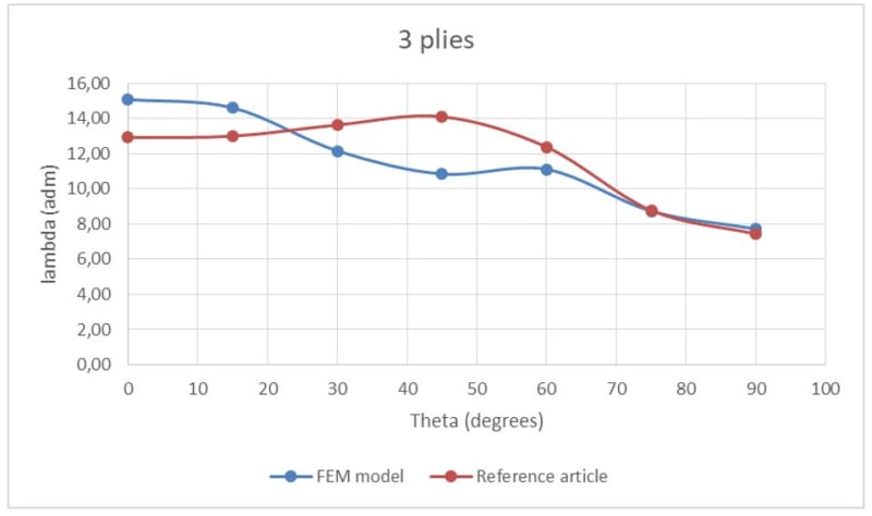
I am trying to identify what could I have done wrong. Does anyone have any idea what I may have done wrong?
The article reference is: BUCKLING STUDIES FOR SIMPLY SUPPORTED SYMMETRICALLY LAMINATED RECTANGULAR PLATES. Yoshihiro Narita. Arthur W. Leissa
Thank you very much!

2_rea4gu.jpg

Capturar_m1adzv.jpg


The model: (the maximum that can be uploaded is 20mb, I had to upload into the drive and share the link.
 
Replies continue below

Recommended for you

The "Plate Mesh" program can address this problem (see the link below). This may help you understand where where the discrepancy is coming from (your FEM or the classical solution).

Another thing to consider is that the classical solution is most valid for A16=A26==D16=D26=0 (discussed in "Practical Analysis of Aircraft Composites"). As those values increase, the accuracy decreases. This is one possible source for your discrepancy. You can check that via observing the A,B,D matrices and also by comparing the results with Plate Mesh. Another possible source is the classical solution itself. I do not have the paper you mentioned, but if it does not account for G12, then it is missing a factor. You may want to look into the solution that uses D11, D12, D22, D66 from the [D] matrix. This solution is also in Practical Analysis of Aircraft Composites, but I believe it is also in MIL-HBDK-17 (which is free).

Plate Mesh -
Brian
 
Hi again!
So a used your Plate Mesh program and the results were quite well, following the tendency and with a peak at 45°. I also checked the ABD matrices of my model on Femap, they were like you said: the D16 – D26 and A16 – A26 increases with the ply angle until get to 45°, where they are equal, then it stars to decrease until 90°. I tried to do a new finite element model on Femap using “solid laminate” but still I didn’t get right results. So my model starts to give bad results for buckling as the D16 – D26 gets higher. Do you have some tip about developing a simple laminate plate model on Femap that would give me right buckling results for all the angles.
Thanks for the attention!
 
Perhaps your "bad" results are not bad. I suspect the classical solution is less accurate and PlateMesh to be more accurate. Perhaps you should plot the PlateMesh results on top of the other two. If Femap and PlateMesh converge, then that is likely the most accurate approach. The classical solution has limitations so one would not expect it to be accurate for all angles.

Brian
 
Yes, the classical solution is NOT the right solution.

FEMAP is a pre/post processor. What solution code are you using? What element type? What material definition?
 
So the classical solution is not accurate for some angles. In my model, I used 2D orthotropic (MAT8) for the material and PCOMP for property card. I also used the Linear Buckling analysis default on Femap (SOL 105).
The graphic is a little different from the first that I sent here cause I changed in the property card the offset bottom surface (just let the default = ½).
Capture_xymnxb.jpg

So I can used this model only for the first angles and the last ones, for those in the middle I have to find another solution for them. Something like FSDT or HSDT, right?
 
Some things to consider:

1. Regarding transverse shear deformation, this will only come into play if the plate is relatively thick. Using Plate Mesh, you can adjust G13 and G23 to see if there is an effect. Does making those values relatively stiff (increase by 10X) increase the Eigenvalue? If not, that effect is not coming into play. If transverse shear was playing an effect, I might expect a lack of convergence across the board (which is not the case).

2. What type of element are you using for the Femap runs? Have you tried both 4-noded and 8-noded quads with full and reduced integration?

3. We can assume the classical solution is not correct, but I don't know why Plate Mesh and Femap do not converge for some of the angles. In other words, we don't know which is those is the correct answer. However, it does seem the Femap curve has more inflection points than one might expect. The 60 degree data point seems odd to me.

4. If you have access to another solver (such as ABAQUS or ANSYS), you could compare the results (you should still be able to use the same Femap model).

5. Check the boundary conditions carefully. Plate Mesh describes how it applies the B.C., but we don't know what you are using for Femap. Because of the coupling effects that occur for an unsymmetric and unbalanced laminate, you might be applying an overconstraint that only shows up when the angle is not 0 or 90. It may not be a coincidence that there is an issue only when the angle is not 0 or 90 (i.e. the cases where the laminate is unsymmetric and unbalanced).

Brian
 
Also, as mentioned previously, I would try another classical solution that accounts for more terms (sources provided earlier). It may be more accurate. Just use the properties from the [D*] matrix instead of [D] if the laminate is unsymmetric. FYI, the eLaminate program can calculate the [D*] matrix (link below).

Brian
 
First, I checked if the transverse shear was affecting the Plate Mesh model, as you said. The eigenvalue increased when I multiplied the G13 and G23 per 10. So I reduced the thickness until the transverse shear no longer affected the eigenvalue. That way the difference with the reference article was nearly 0%.
Capturar_5_trfgta.jpg


I changed the thickness in the femap model as well, but the results remained the same (non-dimensionalised results). So is not the transverse shear that is affecting my model.

I also changed the mesh from 4 noded to 8 noded, following the way that Plate Mesh distributes the load, the results practically remained the same, the difference was too little.

Perhaps are the boundary conditions that are causing the discrepancy. I read the documents of plate mesh, but I did not quite understand how it applies the B.C. Could you explain to me?

In Femap I was doing like this: All edges Simply Supported
Capturar_4_rsemra.jpg
 
I had forgotten to post the results, but here they are. The problem was with the boundary conditions, it was overconstrained. Now the Plate Mesh and the Femap give me the same results, the difference with the reference article I believe it’s because one use Ritz method and the other use finite element analysis.

resultados_a0ttk4.jpg


With Plate Mesh, I also did some tests to see the influence of transversal shear stress in the model. Using, for example, 45º as fiber direction, the non-dimensional critical buckling load decreased 5% when transversal shear is considered.
 
Thanks for the update. Just to clarify a few points:

1. Plate Mesh and Femap show the same result (both FEA solutions). So this is good news.
2. The classical solution is slightly different from the FEA results for some angles. I suspect this has to do with the presence of shear-extension coupling, which would be a maximum at 45 deg and does not exist at 0 and 90 (consistent with the data). Also, most classical solutions are usually in error when shear-extension coupling is present (and the shown classical solution does not terms to account for this). So unless it were some special case where something cancelled out, it is probably a matter of the classical solution not having the capability to account for shear-extension coupling. I don't think the difference is is FEA vs Ritz though.
3. Accounting for transverse shear stiffness has an effect, but is minor in this case (and usually is for thin laminates). If the laminate was thicker, the effect would be more prominent. It will also depend on the material systems and other factors.
4. On a side note, errors in boundary conditions are perhaps the #1 problem for FEA models in general. This was shown earlier in this thread and is a good eminder to to always check/think and get sometimes get a second opinion about them. That was done in this case, which led to a resolution.

Brian
 
Status
Not open for further replies.
Back
Top