Continue to Site

Eng-Tips is the largest engineering community on the Internet

Intelligent Work Forums for Engineering Professionals

  • Congratulations SDETERS on being selected by the Eng-Tips community for having the most helpful posts in the forums last week. Way to Go!

Large Through Bolt in Concrete Column for Support of a Bridge 2

Status
Not open for further replies.

STrctPono

Structural
Jan 9, 2020
706
We are needing to build a bridge over an existing bridge as an emergency support system. I need to anchor the support brackets for the new bridge to the existing concrete bridge pier columns. My concern, and the thing that I am not too familiar with is the torqueing of the through bolts that will pass through the column and essentially hold this entire structure up. We have (10) 2-1/4" Dia. Through-Bolts. In order to core all the way through the 4ft thick column, I'm afraid that the Contractor may need to upsize the diameter of the core hole. If this occurs, I will need the torque in the bolt more than ever to establish a clamping force to avoid the support brackets from slipping.... which would be detrimental.

EFCO has similar systems and they torque their 2" dia. through bolts to 1800 ft-lbs. Unfortunately, I am not aware of SSTC, AISC, or RCSC providing any guidance for these large of bolts. AASHTO has something in their signs and luminaires manual but it's sort of ambiguous. Does anybody have any opinion on this matter or guidance on how best to establish a torque value for a 2-1/4" dia. F1554 Grade 105 threaded rod?

 
 https://files.engineering.com/getfile.aspx?folder=d05d2f46-8438-4382-9bf3-dfb1f608ece4&file=Capture.PNG
Replies continue below

Recommended for you

If both the 2" and 2 1/4" threaded rods have the same thread pitch (4.5 threads / inch) and the two sizes use similar steel, an approximate value for the 2 1/4" rod torque would be the ratio of the thread rods' tensile stress area times 1800 ft-lb. That torque should put roughly equal tensile stress in both threaded rod sizes.

I have not preformed the precise calc, but the answer will be very close to (2.25)2 / (2.00)2 x 1800 ≈ 2300 ft-lb.

 
Thanks SRE. That makes sense. And I agree with you that both bolt assemblies should have 4.5 threads per inch (per AISC Table 7-17). EFCO bolts use 90ksi yield strength material (just verified). F1554 rods are 105ksi yield. So if I use a relationship between torque and tension:

T = (K D P)/12

*Assuming nuts are lubricated
**Using Effective Bolt Diameter

EFCO: P = (1800 * 12) / (0.10 * 1.78)...... P = 121,000 lbs which is 49,000 psi or 54% of the bolt yield stress.
My Situation: P = (2300 * 12) / (0.10 * 2.03)...... P = 136,000 lbs which is 42,000 psi or 40% of the bolt yield stress.

Does this seem correct? If so, I can adjust the torque to achieve my desired tension (which I'm not even sure if I know exactly what it should be). The other issue being that the nut is not lubricated and they over tension the bolt but this is not a problem unique to my situation as this is common in high strength bolting.
 
STrctPono - I'll leave the detail calcs to you, but for the approximation, I would just include the ratio the yield stress:

(2.25)2 / (2.00)2 x 10⁵ / 90 x 1800 ≈ 2700 ft-lb

Before accepting that number, I would do the same calc for fasteners with known torque, say, 1 3/4" compared to 2".

Even if it checks out, I would lower the torque to, perhaps 90% x 2700 ft-lb ≈ 2400 ft-lb. With 10 bolts, there will be random interference between the bolts and the (probably slightly & randomly misaligned drilled holes). IMHO, slippage is not likely.

A complementary approach is to epoxy inject the annular space between the bolts / drilled holes. Check with Sika. For a repair in the 1990's we had to bond large rebar that passed through drilled holes in reinforced concrete columns several feet thick. I believe they had a product that worked for that purpose.

 
Thanks again. I had a debate with a colleague last night about whether we could let them core larger holes and epoxy grout around the annulus. I did not think it was possible but he did. I will reach out to Sika to ask them if they have experience with this. I would much prefer to grout the holes if possible.

My concern is that I have 550 kips of reaction coming down each side of the pier from the bridge above. If the ballpark value of 136,000 lbs clamping force is correct, that means I would need a static coefficient of friction of 0.4 between the steel brackets and concrete to avoid any issue of slip. This sounds about correct. Either that, or I would need to justify increasing the clamping force. I will check some torque values from other known bolt assemblies.
 
Easy enough to overcore and grout or epoxy fill.

You can inject, or you can use a self levelling product.

This sounds more reliable to me than relying on friction.
 
STrctPono:
I would be somewhat concerned about creep of any thick epoxy grout in a large thickness annulus. And, I don’t like anything all-thread in these applications. I think you are going to get bolt bearing and some bolt bending in this type of application. You might look into Mechanical Tubing, it comes in many o.d’s. and i.d’s. (thus, wall thks.), so can likely find a piece of pipe or mech. tube with an i.d. which matches the i.d. of your bolt. Then, when you grout the outer annulus, you are dealing with a lower bearing stress btwn. the tube and the conc., and a much cleaner hole for the bolt and its bearing. For a permanent structure like another bridge, subject to vibration and temperature expansion and contraction and general movement, I sure would like to cut a bearing shelf into the piers. Then I would put a bearing lug on the bracket pls., to be grouted (dry packed) into place after the bolts are tightened. I would not want to count only of friction for these bridge support connections.


STrctPono :

I have experience with large dia. preloaded anchor bolts . I would like to express my concerns regarding the preloaded through bolts to mobilize friction btw bracket and concrete surface.

IMO, in this case ,it is not reasonable to rely on friction . My concern is , due to relaxation ( due to creep , could be more than 50% ) , the preload and so the friction may drop to threshold levels ..

I will suggest epoxy filling the annular space and rely on the bearing of the through bolts .You may speak with HILTI , SIKA etc for the type of epoxy and injection method.
 
Tomfh/HTURKAK,

I agree that the grout around the annulus is a better system. It would be nice to approach this with a belt and suspenders type mindset and grout the holes as well as torque tensioning the threaded rods. I wonder if there will be any issues grouting the holes and THEN torqueing the rods....? The preferable way would be to tension and then grout but it's hard to imagine that being feasible. I am trying to get in touch with a couple different manufacturer's to discuss this. I have no experience with grouting rods in this type of scenario and will needs some guidance.

dhengr,

Duly noted on the creep issue of the epoxy grout. Perhaps a neat cement grout would be more appropriate but will need to check at what annulus size it would be appropriate. So you are suggesting to grout the mechanical tubing in the core hole and then pass the threaded rod through so that the two have intimate contact? BTW, This is a temporary emergency support for an existing bridge. It will only be in service for 5 years so it's not permanent. Otherwise, I would certainly agree with you on wanting to utilize a bearing shelf.

Thanks all!
 
Grout them to ensure bearing. You cannot rely on clamping in this situation.
 

I think also the preferable way would be to tension and than grout. I know there are filling washers for this purpose but the commercial available size limited with M 24.

If i were in your shoes, i would consider the following steps;

- Install the bolt with filling washers at both sides ,
- tighten the nut to design torque ( in this case say 40% of the bolt yield stress )
- Fill the gap with epoxy injection
- Make sure the filling washer hole is at upward at the opposite side (12 o'clock ) and see the epoxy is leaking before stopping the injection ..

You may search the web for ( Verfüllscheibe VS , or filling washer to see the detail). In your case, the washer should be machined from CS plate wtih thk . say 20 mm. There will be a filling hole and a access channel ( grooved at one side from hole to perimeter ).

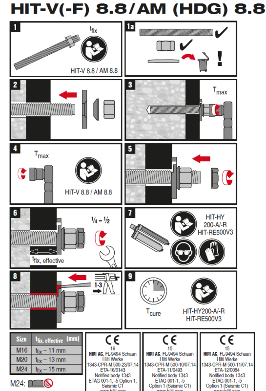
I will suggest you to look the ( Hilti Dynamic/Filling set ) the following picture. and try to get in touch with SIKA and HILTI people..

HILTI_dyn_set_nxd2pp.png
 
You would struggle to fill the whole core via those washers.
 
In this situation, I would consider grinding out the concrete to recess the plate and grout under and around it, so you have direct bearing along the edges of the plate, instead of relying on solely on friction.

Rod Smith, P.E., The artist formerly known as HotRod10
 
HTURKAK. Those are interesting washers. I did not know they existed. It does look like they are intended to fill the annulus between the bolt and steel plate only. As Tom said, I wonder how much penetration you would get with those into a 4ft hole... I will look into these further. Thanks.

Bridgesmith, that would be difficult. 2" recess is all I could get anyway due to the presence of the rebar in the column. That wouldn't provide much of a ledge and not much capacity
 
2" recess is all I could get anyway due to the presence of the rebar in the column. That wouldn't provide much of a ledge and not much capacity

The capacity would depend on the size of the plate, but would be limited by the crushing strength of the grout along the edge of the plate or the crushing strength on the concrete at the interface with the grout.

If you've got a high shear load, you may need to consider additional epoxied anchors to distribute the load to the concrete, in addition to filling the annular space around the primary threaded rod, due to the limitations of the bearing capacity of the concrete around the hole.

Rod Smith, P.E., The artist formerly known as HotRod10
 
Why does it need to be pretensioned prior to grouting?

cast in rods, chemical anchors, ordinary reinforcement, etc are rarely pretensioned prior to grouting. Ordinarily the grout/cement/epoxy is allowed to cure the the bar is loaded.

What’s so different here?
 
STructPono - IMHO, the thru bolts create more problems than they solve. The biggest problem for the Contractor is to maintain alignment of relatively "small" (2 5/8") holes drilled through 4' of heavily reinforced concrete so that the bolt pattern on the column's far side is matches the bolt pattern on the column's near side (within reasonable tolerance). If the patterns do not match... what does the EOR do then?

During my time as a bridge contractor bridge work was exempt from "routine" building code requirements, if this remains so:

Instead of thru bolts, I suggest creating your own "large" post-installed anchors for use on both sides of the column. Hilti offers technical data to do this for anchors up to 2 1/2" diameter.

 
SRE - I will admit that I scoffed the first time I read your suggestion for eliminating the through bolts for post installed anchors. Upon further reflection, it's actually a good idea and I'm warming up to it. I have (10) 2-1/4" anchors per support. 6 total supports. The top row of anchors (2 total) are non-debatable. These resist considerable tension and shear in two different planes and must remain as through bolts. All the anchors below these are shear only which could work out with a post-installed anchor so long as we have enough embedment. I will contact HILTI about the larger anchors and what they have tested. This of course complicates things as this requires two different processes, core sizes, different materials, but could save time and headache in the end.

I did end up solving the issue with the top through-bolt anchors. We're going 3" dia. core hole, place cap seal each end (to seal and centralize rod), drill and install injection ports, and pump one of Sika's non-sanded grouts into the hole with an bleed hole on opposite side. Thanks for all the suggestions on this and the push to grout these in place.

Tom, it's not essential, but I would rather not stress the grout in the hole. I worry about it jeopardizing the grout right near the surface with that much tension in the rod. True, other systems are torqued too, but (to my knowledge) not to the same level as we are planning on doing. Typically, post-installed systems are very lightly torqued. Other than highway sign structures, high-mast lighting, or transmission towers, I've never seen CIP anchor systems torqued to anything specific. I could be wrong in this.... Also, with it being done this way, the Contractor will now need to torque the rod from both sides of the column which adds an extra step.
 
On a past project I did something similar, but with smaller dia 150 ksi PT bar, and different end-application:

1. core horizontal through-holes
2. drill small dia angled holes at each end, vertically above the center of the core hole, with the small holes intersecting the core hole at approx 45°;
3. clean the holes;
4. install anchor rods, plates, nuts and washers
5. using a pull-bar and stressing stool, hydraulically stress with a hollow ram each rod to required tension (torque is not a reliable method of achieving a desired tension);
6. sealant/caulk to perimeter of anchor rod bearing area at each end, and thread/washer of each rod;
7. using plural component epoxy injection pump with low viscosity resin (<500 cps) inject the annular space and 'bleed' the resin to opposite end, then cap;
8. repeat.​
 
Status
Not open for further replies.

Part and Inventory Search

Sponsor