Continue to Site

Eng-Tips is the largest engineering community on the Internet

Intelligent Work Forums for Engineering Professionals

  • Congratulations KootK on being selected by the Eng-Tips community for having the most helpful posts in the forums last week. Way to Go!

Lateral bracing of tension flange 1

Status
Not open for further replies.

mn4st

Structural
Apr 21, 2016
6
When do we need to brace the tension flange? Any help would be much appreciated. I found this picture on CSSBI website and can't find a reason for bracing the tension flange. It's not a cantilever or Gerber system. Could it be the wind suction force (extreme wind zone) that reverses the tension-compression in flanges?
Untitled_picture_ct5sqm.png
 
Replies continue below

Recommended for you

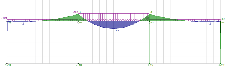
It could be wind uplift buy it also appears that you've got moment connections at the ends of those beams. As such, there may well be hogging moments and bottom flange compression. The original designer may well have specified the bracing to limit the unbraced bottom flange length for this reason.

 
May need to keep the recommended KL/r to 300 or less for a tension member.

Not directly applicable to your situation but.......also, in the bottom chord of a truss (usually in tension), you have web members in compression that will want to buckle out of plane. You will need lateral support of the bottom chord to provide out of plane buckling stiffness at the nodes of compression members.
 
I would tend to put my money on the wind uplift as well. I likely would have put the brace closer to the support if I was concerned about moment reversal at the support, and maybe even kicked it to the MF beam rather than the adjacent infill beam. There's no reason to brace the infill beam for bottom flange compression due to support conditions since it looks like a knife plate to the perimeter MF beam. That makes me think your initial impression (wind uplift) might be right.

That angle looks awfully spindly to me for a bracing member, but maybe the perspective is making the length of the angle seem greater than it is.
 
chucklesNOLA said:
I likely would have put the brace closer to the support if I was concerned about moment reversal at the support

I had that same thought. But, then, given how short the span is, I could see it making more sense to have the central brace rather than, say, 1/3 point bracing which would seem overkill for a beam that short. I'm guessing that this is either:

1) Just wind uplift bracing or;

2) An elegant answer to both wind uplift bracing and gravity induced bottom flange compression.

 
This is just speculation, the designer may be trying to reduced the braced length of the bottom flange for an unbalanced loading situation which would create larger lengths of negative moments in the adjacent members:

FRAME_ygnrde.png
 
Thank you all for the comments.
 
Bracing the bottom flange is required for intermediate and special moment frames. Look up "beam stability bracing" for moderately and highly ductile members in AISC 341. Section D.2 in the specification (page 9.1-14) gives requirements for the bracing. As others have said it is due to the bottom flange being in compression when frame action occurs.

But it may be uplift bridging if these are just ordinary moment frames.
 
Would we all consider the continuous element attached to the bottom flanges in OPs picture as bracing? Wouldn't it need to kick up to diaphragm or terminate at a lateral resisting element(and perhaps it does out of frame somewhere)?

Open Source Structural Applications:
 
Celt said:
Wouldn't it need to kick up to diaphragm or terminate at a lateral resisting element(and perhaps it does out of frame somewhere)?

I assumed that it did kick up or brace somewhere along the line. I'm happy to leave that part of it in OP's hands.

 
Celt said:
Would we all consider the continuous element attached to the bottom flanges in OPs picture as bracing?

Nope. Especially not for IMF/SMF bracing. If it were MF bracing youd expect to see it closer to platic hinge, d or 1.5d from furthest flange plate bolt but outside the protected zone I think.

Even assuming that there are some X's or other termination anchorage theres not even any tabs/gussets at the beam fillet for a decent weld or bolt. Ive seen a handful of PEMB frames that skimp on bot flange bracing (L1.5x1.5 from purlin/joist to bot flange) and hit it with a one sided fillet weld right to the beam's fillet(weld since PEMB). Superb detail... OP's pic looks similarly frail.

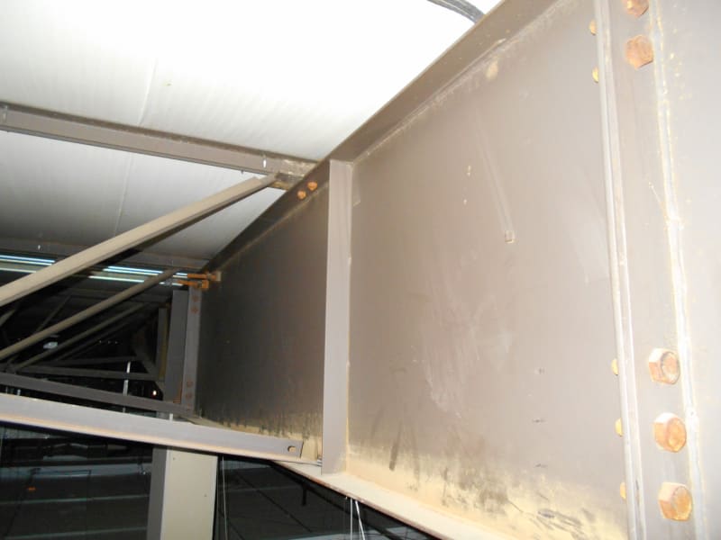
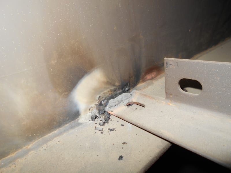
Found the pics. See below. This particular specimen appears to be very tired.

DSCN0154_l3ygxg.jpg

DSCN0155_mgsfhw.jpg
 
Would we all consider the continuous element attached to the bottom flanges in OPs picture as bracing?

If you connect enough of them, then its possible to show that they have the same effect, forcing a higher mode of buckling. The concept is similar to the fact that if you brace a column to another column, then the axial capacity of the first column about that braced axes is the sum of the axial buckling capacity of both columns. In practice though, a few braces up to the slab take out any uncertainty!
 
Status
Not open for further replies.

Part and Inventory Search

Sponsor