Continue to Site

Eng-Tips is the largest engineering community on the Internet

Intelligent Work Forums for Engineering Professionals

  • Congratulations GregLocock on being selected by the Eng-Tips community for having the most helpful posts in the forums last week. Way to Go!

Lateral Earth Pressure from Surcharges and the 2X factor 1

Status
Not open for further replies.

Doctormo

Geotechnical
Jul 20, 2011
150
I would like to revisit lateral earth pressure from surcharges as it pertains to classical earth pressure theory (Coulomb/Rankine) and elastic theory (Bousinesseq) since it has bothered me for years. At the same time, I want to look at the argument for doubling Bousinesseq values.

When I look at a simple uniform surcharge condition on a vertical wall with a phi = 30 granular material, the lateral pressure relationship is Q x K with K being defined by the phi angle and wall displacement condition whereas Bousinesseq is typically simplified based on a Poisson's ratio of 0.50 and the phi angle is not part of the calculation. If the Bousinesseq strip load formula is run with no setback from a wall and an infinite depth to simulate a uniform load, a K value can be calculated also. So here goes:

Coulomb Ka = 0.297
Rankine Ka = 0.333
Ko condition = 0.500
Bousinesseq = 0.500
2xBousinesseq = 1.00

By this comparison, doubling Bousinesseq is twice the Ko condition and three times the typical active earth condition which seems to be unreasonable for most conventional retaining structures. I have never been able to accept the 2X factor for conventional retaining walls for that reason alone.

It sure seems to me that doubling the Bousinesseq values would be a function of a non-yielding wall that essentially pushes back against the load imposed and does not allow the soil to do any work (worse than Ko condition in some way?). You could use compacted crushed stone for backfill and the simplified Bousinesseq formulas in all the handbooks and textbooks would yield the same pressure increase so there is certainly a limitation to the simple formulas in practice.

Equally perplexing is that most retaining walls would be designed for active earth pressure for the base soil pressure then the surcharge would be added based on some sort of higher Ko condition or more which seems to be a little bit of adding apples and oranges together. If one was to use Bousinesseq then should the wall be designed for the Ko condition starting out?

It is not that I don't like Bousinesseq theory in concept but it fights with classical active earth pressure theory and wedge theory which is lot simpler to understand than elastic theories and of course, calculus. Both theories coexist in the same section of almost all text books yet they have never agreed in magnitude (or force location). Bowles made a stab at explaining some of the differences (such as with Spangler's testing) but everyone else leaves all the theories in the books with no comparison.

Just like to see what you all think about this since it never seems to get resolved.


Replies continue below

Recommended for you

Good topic and I will need to think about this some, however I would like to point out a couple of things.

1.) Ka and Ko increase linerly with depth where as the Bousinesseq funciton is a half light blub shape, therefore the resulting pressure is differnt than what would be obtanined by using Ko.

2.) The 2x factor comes from experiments by Spangler and others (forgot who). Spangler in his Soil Engineering book explains this result is do to the wall being rigid and not allowing the soil to deform as it would if soil were present. When you see formulas for surcharge in most design manuals they usually refer to Terzaghi's modified equations as I beleive he further modified the equations to better fit the expiermental results. Spangler does allude to the fact that if the soil is allowed to deform by 'about' the same amount that it would to mobilize active pressure than the surcharge pressure would not need to be doubled.

So I guess I do agree that if the surcharge estimates maybe conservative however they are....estimates.

Hopefully someone else can elaborate....

EIT
 
Conventional earth pressure theory is rooted in friction angle or cohesion. Elastic theory is rooted only in the assumption that it's an elastic medium and there is some Poisson's ratio (i.e., there is no reference to soil strength).

Active earth pressure requires some movement to mobilize the strength along the Rankine failure surface (granted it didn't fail). We approximate (closely approximate) the affect of a surcharge by using a rectangular distribution. Is it really rectangular? Well, it would seem so. . . It would seem that once you get beyond the extent of the Rankine failure plane, the surcharge would have NO effect. Unless the presence of the surcharge changes the actual location of the failure plane (ala Coulomb).

How would you (we?) evaluate a point-, line- or areal-load surcharge adjacent to a cantilevered retaining wall if the wall was built many years ago? Would we assume that the wall had moved to mobilize the active earth pressures? Would we assume that the new surface load would lead to more movement, but that'd be o.k.? Would we want to be conservative and evaluate the loading conditions as if we don't want any further wall movement? Would we just be engineers and consider what's best for that specific project? I'm going with the latter. I'd want to make sure that wall was buttressed or otherwise supported for the new loads and I'd likely want to limit further movement.

I do like the OP though. I want to look at the effect of modeling an areal load using a rectangular distribution from Ko and also modeling the areal load as a series of closely-spaced point loads using elastic theory. I suspect they'll be different. Not sure which way I'd go though. . .

f-d

¡papá gordo ain’t no madre flaca!
 
Thanks for the responses.

RFreund:

1) The bulb shape is the result of offsets and load widths in the elastic formula, I used the example of a zero offset and an infinite load width in the strip formula for a uniform load which results in a rectangular pressure distribution with a Ka = 0.50. For phi = 30, the Ko is the same coincidentally.

2) Bowles explains his position on the Spangler testing and I tend to agree that this testing was suspect. It seems that this theory has not been tested enough in real life due to the expense of full scale testing while lab testing of soil structures is always suspect in my opinion due to the small size of simulation. It also never rains in a lab, fills are not built in six months, and so on :)

f-d:

Good points, my observation is based the obvious difference between elastic theory and wedge theory. The pressure distribution of an elastic strip, line or point formula is bulb shaped as noted above while wedge theory will provide a completely different distribution from a strip surcharge. In your Rankine wedge example, a strip load in the front half of the wedge will provide a lot of pressure at the top of wall and less in the lower section. If the strip load is near the back of the wedge, there will be no pressure in the upper part of a wall and most of the thrust will be in the lower part. In either case, the total thrust is about the same but the distribution is different. The trial wedge method discusses surcharge pressure location based on influence lines vs. elastic theory.

Bowles actually discusses this also and concludes the wedge theory may overestimate the total load and the Bousinesseq distribution may result is less total loading on the wall for a strip load. Of course, he is not so correct if one doubles the formula load.

The other problem with Bousinesseq formula that you have touched on is that it will surcharge a wall regardless of offset because it is an elastic formula for the infinite condition. Obviously, at some setback from the Rankine angle to 45 degrees, the surcharge will be unable to affect the wall in any manner based on simple force vectors so elastic theory has some real world limitations.

The subject has confounded me for years and there may be no right answer. If I am placing a large building footing on the fill behind a retaining wall, I would probably do a wedge analysis and Bousinesseq analysis and add the two pressure diagrams together (rectangular pressure) to be safe since the risk of any wall related problem is too great. On the other hand, getting too carried away with theory can lead to overly conservative designs when they are not necessary.


Doc - Sorry I think I misintterpreted your posts the first time. Also I don't think your attachment loaded correctly.

I have attached a spreadsheet that has different tabs (sheets) using different methods for analysing offset surcharge. It may be hard to follow. I'm actually hoping to create a blog post review different surcharge techniques in the next couple weeks. The problem with my spreadsheet is that I really need to learn how to use VBA to create a contracting or expanding database based on the number of discreatized points that are used. I would also like to add a trail wedge method or maybe a culmans graphical trial wedge method, but I'm not too sure how to format it.


EIT
www.HowToEngineer.com
 
 http://files.engineering.com/getfile.aspx?folder=46e4e74b-9538-4f37-ac1e-4c61b24d12c1&file=Offset_Surcharge_All_Methods.xlsx
I guess the "bulb" discussion resonates more with me as a vertical stress change concern. I'm thinking more about what's happening on a vertical slice parallel to the back-side of a wall (or reinforced zone). I need to think some more on this though. . .

f-d

¡papá gordo ain’t no madre flaca!
 
RFreund - Sorry, I did not attach anything, must of touched something by mistake.
I am only looking at the Bousinesseq vs. trial wedge methods where the lateral pressure diagrams differ a lot for a strip footing and/or offset loading. Bousinesseq will have the pressure increase in the upper part of the wall whereas the trial wedge will have the pressure increase in the lower section of the wall based on a 1:1 influence line more or less. For example, a 5' load offset would begin the surcharge at a depth of 5' vs Bousinesseq having maximum pressure just a few feet down from the top. I wish I had time to put something together but too busy at the moment.

f-d: Sorry, I meant the bulb shape of the lateral pressure from a strip loading not the vertical pressure bulb under a footing although some people try to relate the two. I am looking at the vertical interface as well for a wall or reinforced zone.

I have programmed trial wedge analysis and it is pretty easy if you don't have wall batter and broken back slopes to deal with. It gets a little messy when all parameters are accounted for. You can use the Rankine or Coulomb models and get a quick answer for vertical walls and level back slopes. The fact remains that the two surcharge pressure diagrams are quite a bit different.
 
O.K. so now I'm a bit confused. . .

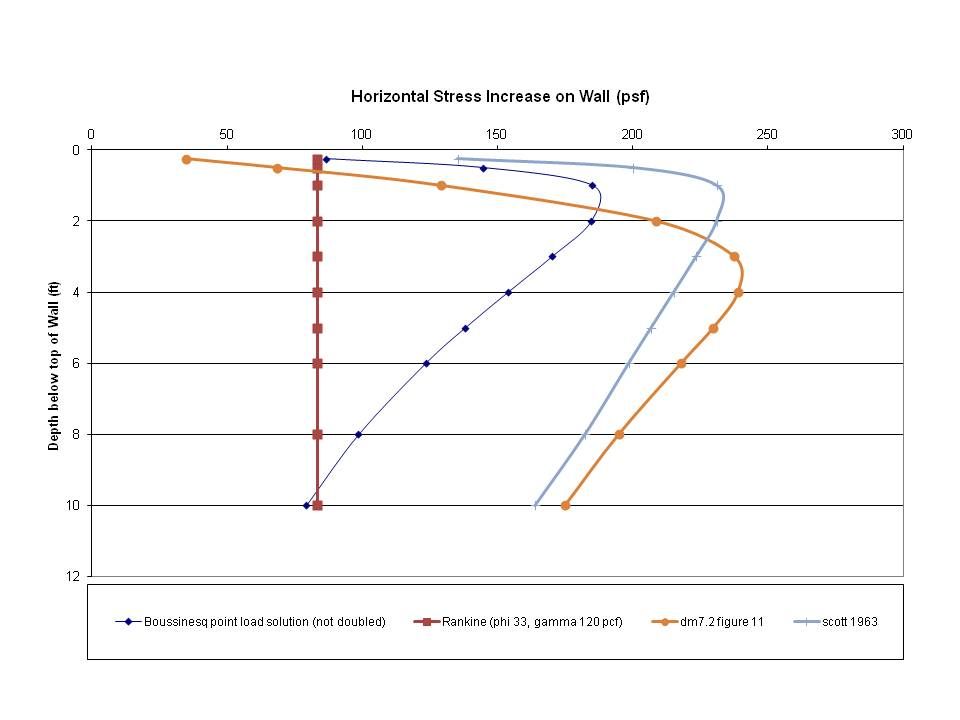
The attachment shows several hundred point loads spaced 1 ft on centers. The realm of the point loads extends 10 ft to either side of the wall measuring point and 36 ft back from the wall face. This is to typify an areal load of 250 psf. I used the Bousinnesq horizontal pressure equation. and contrasted those results to the horizontal stresses that would emerge from the Rankine theory. I did not double the Boussinesq results. It looks like I did in the upper 5 ft or so when you contrast the Boussinesq to the Rankine.

I have no idea what this study is telling me. . . I almost feel that the doubling effect makes more sense for a singular load, or a series of singular loads in proximity to and parallel to the wall face. I feel if the series of loads are perpendicular to the wall face the closer point load might-should be doubled but the ones back from the wall face have the closer loads acting as the "image" load, thus rendering the doubling effect irrelavent. Don't know. I just know what the results look like.

Have a look at the attachment.

f-d

¡papá gordo ain’t no madre flaca!
 
 http://files.engineering.com/getfile.aspx?folder=108aaece-4440-4ba1-bb86-baaf9fe4d435&file=horizontal_wall_stress_study.pdf
Let me add my thoughts. It seems the reason we are discussing this topic is to get a handle on the global factor of safety. Looking at the entire soil and structure system (soldier beam or conventional retaining wall, tieback walls, etc) we have many inputs. It consists of soil sampling disturbance, laboratory testing procedures, assigning Ka or K0 or in between value, the 1x or 2x factor for surchages, using 0.66Fy or 0.6Fy, overstress factor, passive wedge input, tieback design methodolgy and connection design of walers, etc. It seems that each of the above calculation steps has some factor of safety built in with it. The combined system may or may not be overdesigned.

It defeats the purpose for example to be careful in the geotechnical testing & analysis and in the end use the conservative FHWA method for designing tiebacks. Similarly, to design an earth retention system at just above the required F.S. and yet not consider bottom heaving or soil piping analysis. Looking at the entire system is how we can judge the overall built in safety factor.
 
f-d: I attached a quick earth pressure comparison plot I did similar to yours and based on simple Rankine pressure plus a Bousinesseq and trial wedge surcharge added to the Rankine values. Hopefully I did not make any major mistakes in my haste. This is based on the Bousinesseq strip load formula with a 500 psf load at a 5' offset and a 15' load width. The Bousinesseq distribution is very sensitive to load offset and load width whereas the trial wedge distribution is primarily controlled by offset so long as the load width is wide enough to cover the trial wedge area.

The silly part about Bousinesseq and elastic theory is that one can vary the load width from 5 feet to 1000 feet and the answers and curve keeps changing albeit small after a point. Trial wedge has a similar problem with sloping backfills where the zone of influence can be nearly infinite at times. However, trial wedge analysis will have no surcharge influence on the wall at a depth approx. equal to the offset which is the principal difference I am after.

From my plot in this particular example, the total thrust may be in the same ballpark but the distribution is different. This may not be such a headache for cantilever walls but gets more interesting with soil nail and MSE walls where the pressure distribution becomes more important. Bousinesseq can not deal with backslopes so the theory is limited to simple analysis and not as flexible as trial wedge analysis. Part of my issue is also the concept of adding a Bousinesseq pressure to a Rankine or Coulomb pressure which are based on two different theories.

FixedEarth - Overall system reliability or "global factor of safety" is another issue altogether. All of the civil engineer profession has this problem where conservative assumptions can be piled on each other and the overall FS can be extremely high. The same can be said for unrealistic assumptions or methods of analysis which goes the other way. In this case, the methods provide different answers which is the start of these problems not unlike picking equivalent fluid pressure over a Coulomb analysis (maybe 25% less pressure) or using 34 degrees and 125 pcf for aggregate base material which is both low and high at the same time. This could be its own thread.
 
 http://files.engineering.com/getfile.aspx?folder=e8521310-a796-4b44-a1d7-e1c160db83ec&file=Surcharge.pdf
Doctormo,

I like your plot. The only issue I have is you are using Rankine earth pressures from the soil below the ground surface. This force triangle is present with zero areal, line or point loads. For areal surface loads, the change in horizontal stress is defined by a rectangle as shown in my plot. It's just q-surcharge*Ka and does not attenuate with depth.

FixedEarth,

I agree with Doctoromo. When you get in the weeds, get in all the way. Fortunatly, I know how to get out of the weeds too! My approach to these problems is to fully understand the details and then (only then) temper those details with the practical aspect of where we have true knowledge. For now I'm in the "A" part. I'll emerge in time. . .

f-d

¡papá gordo ain’t no madre flaca!
 
f-d,

We are on the same page. The Rankine surcharge in my plot begins at a depth of 6' due to the offset via trial wedge and is roughly 150-160 psf at 10'+. The uniform Rankine surcharge would be q*Ka = 500 psf x 0.333 or 167 psf per the equation. The trial wedge solution matches this value for a uniform surcharge with no offset but the load offset creates a situation where the loading approaches the maximum value with increasing depth but never reaches it.

It is easy to visualize as the uniform q loading is not applied over the entire failure wedge due to the offset so the lateral load can never be as much as the full surcharge loading condition per the simple q*Ka equation.

My concern is the shape of the curves and where the surcharge loadings are applied as they are quite different. I used an example where the two curves look reasonable but they can look completely different if I used a higher loading and smaller strip width such as footing load which would create a large pressure "bulb" near the top of wall which dissipates rapidly with depth under Bousinesseq whereas trial wedge would show no effect until a depth of 5'+ and dissipates slowly with depth for a strip load.

How can they both be correct with such differences? Elastic and wedge theory are both reasonable in concept but fight with each other in practice. I tend to favor wedge theory because I understand it better but a large surcharge adjacent to a wall may result in a pressure spike that may eventually dissipate with time and wall movement. Almost a short term/long term consideration of the loading in my mind.

I still can not reconcile the 2X factor on Bousinesseq formulas for ordinary loadings and retaining walls though. It is too much different than wedge theory and active earth pressure for most applications unless movement is restrained.
 
How about this publication:


Scott (1963) gives a formula for strip loading as shown on page 230. I ran that equation and it worked out very similar to the chart takeoffs of DM-7.2.

horizontalstressstudy2_zpsce51f296.jpg


the dust is still settling. . .

f-d

¡papá gordo ain’t no madre flaca!
 
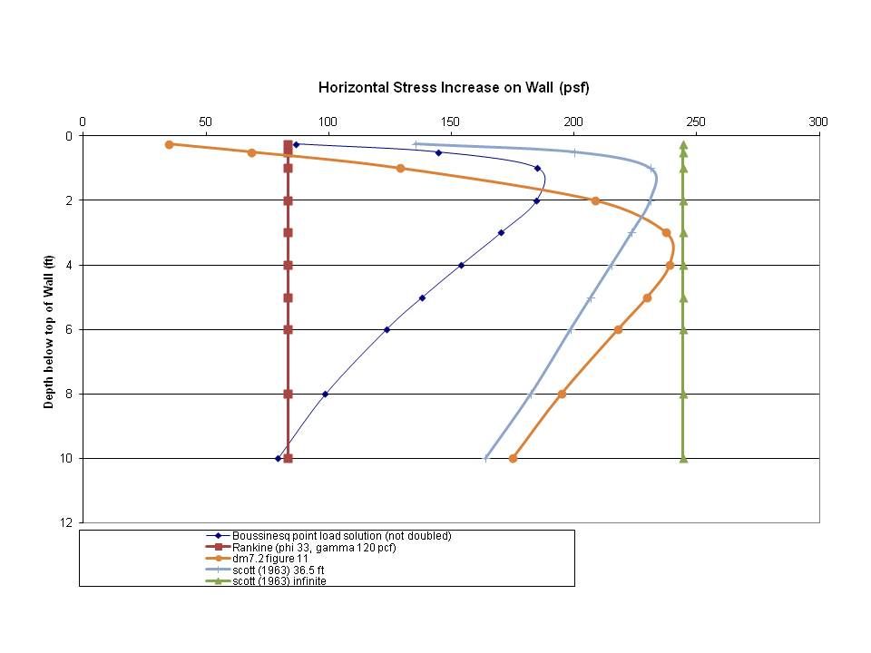
p.s., I'm using 250 psf and a strip load that begins 0.5 ft from the wall face and extends 36.5 ft from the wall face. for all practical purposes it's the same as an areal load.

f-d

¡papá gordo ain’t no madre flaca!
 
f-d,

You are almost there and will get to observe the results. Enter 500', 1000', and 5000' as the load width into the strip load formulas for the "infinite" situation and watch the results. The answer will become a uniform 125 psf lateral pressure (or 250 psf if doubled). Bousinesseq laughs at 36.5' being an infinite condition and still provides a significant reduction with depth which is hard to imagine. How can soil exhibit an elastic response based on things happening 100 feet away? Your curves appear to be using the 2X factor also

Many equation solution are integrated? (argh, watch out when I talk calculus) over an infinite condition to arrive at the short form equation. The Coulomb equation with a backslope is a good example of this. Sometimes you have to run a trial wedge over an enormous lateral distance to match the equation Ka to a couple of significant figures as the wedge chases the backslope. This typically occurs when the shear strength and backslope do not differ by a lot or a seismic coefficient is introduce.


Yeah, like I can integrate. . .

So, using Scott's method and running the areal load from the wall face to some infinite distance away from the wall, you are correct, the horizontal wall load becomes rectangular at (about) the value of the areal load (in my case an areal load of 250 psf).

This doesn't make any sense! So, you have to figure that this is some mathematical matter. I mean if we return to the vertical stress "bulb" at some point there is a practical limitation on how much vertical load can be conveyed to the wall. If there is no truely measurable vertical stress change then there's no correlated vertical component.

So, what's the practical approach? Yeah, that's a rhetorical question. . .

horizontalstressstudy3_zpsb9917952.jpg


f-d

¡papá gordo ain’t no madre flaca!
 
sorry, I meant to say, there's no correlated horizontal component.

f-d

¡papá gordo ain’t no madre flaca!
 
f-d,

See, you are coming around to seeing the problem I started this with. The elastic theories are highly theoretical and conflict with active earth pressure "wedge theory". It seems that one really has to have a restrained wall condition and then apply a large surcharge very close to the wall to realize the Bousinesseq type of loading. The 2X factor requires that the wall must not yield and essentially pushes back in my layman's terms. Once the wall begins to yield (I assume elastic theory has no provision for yielding under load other than the elastic response of Poisson's ratio), the load gets transferred to the wall and wedge which begins to look more like the trial wedge solution.

Watch out for the vertical pressure bulb (roughly 2V:1H) and Bousinesseq lateral earth pressure theory as there is no relationship although it seems like there should be. The vertical pressure bulb is usually used for settlement calculations as I recall and the elastic theory is something else altogether. Trial wedge usually indicates that the surcharge influence is more like 1H:1V unless the load is really large. See my previous plot.

Sometimes I thinke we are just not meant to understand soil mechanics.


re: The pressure bulb. It would (almost) seem that if there is some delta sigma V, you could use Ko to calculate a correlated delta sigma H. You'd think that would give you (yet another) way of considering the horizontal stress distribution. MORE HOMEWORK!

I'm ruminating on engaging my old professors. Later in the month, I'm hosting a conference and jim Mitchell will be there. Maybe I'll talk to him? I'd like to know the answer (or a meaningful approach).

f-d

p.s., you got me thinking, so that's a good thing.

¡papá gordo ain’t no madre flaca!
 
Well, the pressure bulb lateral pressure pushes on the soil next to it which pushes on the soil next to that and so on so when does it stop or attenuate? In any case, using a 2X factor on Bousinesseq seems overkill for any wall that can yield in my opinion.

Good luck with getting any helpful advice. I will be seeing some academics in Nov and might corner one of them on the subject also. I would think Jim Mitchell is getting a little old now to deal with this sort of stuff but you never know.

All the earth surcharge information is contained in the same section of many text books and design manuals yet no one seems to address the obvious question about differences. The same thing can be said for Rankine vs. Coulomb where no one seems to take a position either. The fact that Rankine formulas are simpler to remember does not seem to be a valid reason for using them although the structural community still uses equiv. fluid pressure and other simple concepts.

The different slope stability methods are another area where the factors of safety vary by quite a bit due to method differences so it is not sufficient to specify a minimum factor of safety but one has to state by which method also to be clear.

 
Status
Not open for further replies.

Part and Inventory Search

Sponsor