Continue to Site

Eng-Tips is the largest engineering community on the Internet

Intelligent Work Forums for Engineering Professionals

  • Congratulations KootK on being selected by the Eng-Tips community for having the most helpful posts in the forums last week. Way to Go!

Launch and recovery system (LARS / A-frame) Need some ideas.

Status
Not open for further replies.

BEMPE16524

Mechanical
Feb 17, 2008
362
Hello guys, i have tried to figure out why do they make the base unparallel as in the photo (you can see the hydraulic cylinders as well) but can't think off anything logical.
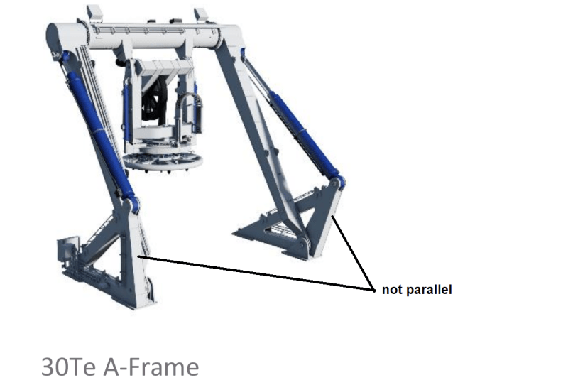
Untitled_a7sxpc.png

appreciate all ideas.

R.Efendy
 
Replies continue below

Recommended for you

In the position shown the LH cylinder is almost inline with all the pivots. If they were all inline the cylinder's force (either push or pull) would not cause the frame to rotate.

Whereas the RH cylinder is still capable of exerting meaningful push pull.

I believe the large diameter tubular main crossmember is required to withstand the different left and right forces at the travel extremes.
 
BEMPE16524:
I suspect hat the RH and LH frames are essentially identical in terms of member sizes, dimensions, locations of pivot points and lifting cylinders, etc. And, that the circular crosshead beam will rotate to allow the load to hang vertically if the operator wishes. The A-frame must rotate out over the rear end and the vessel and back inboard some distance to put the loads back down on the rear of the deck. Do a kinematic study of that frame to see how the lifting cylinders act when the frame is in various positions. The main legs will likely rotate down below a horiz. position off the stern and they will rotate up & back until they get near the rear pivot on the lifting cylinders at which point they will reach one of those lock-up points where the cylinders and too many pivot points line up for the system to function properly.

Tmoose:
Your Monday morning coffee isn’t strong enough yet, or maybe you should put something in it to start the week out right. [bigsmile]
 
They cannot be identical because the mechanism goes over-center. If they are the same then at some orientation the line of action of the cylinders would be in line with the bridging frame and generating no net torque.
 
not seeing it ?

the drill head (?) is pivoting by the arms that go down to the lower lugs. The actuators control the position of the arms. Why have these two actuators at different angles to the base ?

another day in paradise, or is paradise one day closer ?
 
It's so that you can move the frame from horizontal to horizontal past vertical but still have control.

If they were the same then at some point the arms might get stuck vertically.

Remember - More details = better answers
Also: If you get a response it's polite to respond to it.
 
Like on steam locomotives where the cylinders are out of phase.
 
thank you all for your feedback. man that's very tricky to make both LH and RH sync at the transition point.

R.Efendy
 
There are two transition points - one for each minimum length for each of the hydraulic cylinders. Since these happen when the moving frame is nearly vertical the loads on the cylinders are a minimum. Starting from horizontal, retract them both until one bottoms out. Continue to retract the other to go over-center until the other cylinder bottoms out, then allow both cylinders to extend with whatever controls are suitable/safe.

This document shows two of the over center type and one that doesn't go over center:
 
3DDave said:
There are two transition points - one for each minimum length for each of the hydraulic cylinders. Since these happen when the moving frame is nearly vertical the loads on the cylinders are a minimum. Starting from horizontal, retract them both until one bottoms out. Continue to retract the other to go over-center until the other cylinder bottoms out, then allow both cylinders to extend with whatever controls are suitable/safe.
my further research brought me to this image
pic1_2294_ecupmp.jpg


R.Efendy
 
Must be interesting getting the pressure to go from one side of the cylinder to the other as you go "over the top"....

Remember - More details = better answers
Also: If you get a response it's polite to respond to it.
 
LittleInch said:
Must be interesting getting the pressure to go from one side of the cylinder to the other as you go "over the top"....

i imagine the hydraulic logic is not that straight forward which i may not consider for my application. enough for a gist of my knowledge.

R.Efendy
 
One side is grounded outboard, the other is grounded inboard. To pull the load inboard retract the inboard cylinder until it's fully retracted, then extend both. To pull the load outboard retract the outboard cylinder until it's fully retracted and then extend both.
 
BEMPE16524 said:
i imagine the hydraulic logic is not that straight forward which i may not consider for my application. enough for a gist of my knowledge.

It's actually very simple. The point at which each cylinder is at minimum length (and needs to 'reverse') never changes. As long as you know the position of the A-frame, it's very easy to automate the whole process. There are old machines that use this type of mechanism and do it mechanically, with no electronic controls at all. I'm sure on a modern ship, this is all computer controlled, but if each cylinder is valved independently all you need is a couple of switches to make this work.
 
It appears that in this application there is never a case where hydraulic pressure needs the be applied to extend the cylinders, only to retract them.
 
Status
Not open for further replies.

Part and Inventory Search

Sponsor