Eng-Tips is the largest engineering community on the Internet

Intelligent Work Forums for Engineering Professionals

  • Congratulations waross on being selected by the Eng-Tips community for having the most helpful posts in the forums last week. Way to Go!

Leakage Current from the Alternator

Status
Not open for further replies.

vp1959

Electrical
Jan 28, 2012
22
KW
Hi

Kindly review the following for a generator rated for 500kVA, 400V, 3P4W, 50Hhz, fitted with Unrestricted Ground Fault Protection System is tripping on ground fault. Upon inspection we have found:
1) The insulation resistance for all winding are over 1000 M.Ohms
2) There is no leakage from the load
3) The leakage current measured from the alternator body to Neutral is increasing with the load (~1A at 100kW, ~2.5A at 200kW, ~3.75A, ~5A at 300kW and ~6.5A at 400kW.
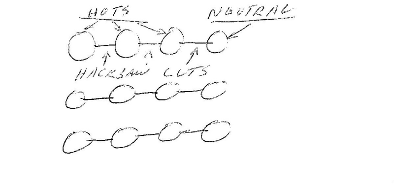
4) The conduit box for alternator is found with steel plate and the plate is magnetizing.

Though the insulation resistance for all windings are found good, we have stripped the alternator, cleaned the windings, dried in the oven, varnished. Removed the steel gland plate and re-tested and found the leakage is reduced by 40%

Questions:
1) What could be the reason for such leakage when the insulation resistance is good?
2) If such leakage is common, what will be the maximum permitted?

Regards

Prakash
 
Replies continue below

Recommended for you

Really we need a diagram showing all connections and grounding jumpers and the location of the CTs.
A description of the loads, and which are connected line to line and which are connected line to neutral.

Bill
--------------------
"Why not the best?"
Jimmy Carter
 
You mean the current in unrestricted ground fault relay when you say 'leakage current' I suppose!
The current is increasing with increase in load and this could be because the neutral current is not taken in to consideration in the ground fault protection.
Verify the CT location for the ground fault protection? It should be in the Star point - to - ground connection of the generator if the protection is based on neutral CT.
If the protection is based on summation of phase CTs, make sure in addition to all three phase CTs, neutral CT is also included in summation circuit.
"The conduit box for alternator is found with steel plate and the plate is magnetizing." - This matters if the cables are single core cables and the impact will be overheating of the gland plate.
I have seen steel plate used with single core cables but there is a break created in the flux path around each cable by making a cut in the gland plate and filling it with brass (non-magnetic material).
 
Hello Mr. Bill & Mr. Raghunath,

Please find attached drawing to have an idea, noting that:
1) The generator is used for feeding two 150HP mud pumps
2) The leakage problem is common with the above site loads and the tests at workshop with a load bank (Resistive load)
3) We have confirmed that there is no leakage from the load (site load and load bank)
4) The there is no separate Unrestricted Ground Fault relay, it is part of the generator controller COMAP, IL-NT AMF-25 (please see the diagram attached). The Ground Fault Trip point set on the DG controller is 60mA, 0.5 seconds time delay, while the actual current measured is 1 - 6.5A at 100kW - 400kW. I think that the 60mA setting is too low for the Unrestricted Ground Fault Protection (upstream protection) and been working for the last two years due to error in the CT. Tripping issue is started only recently, probably due to increase in the leakage.
5) As the cables are single core and were passing through two steel gland plates, we have tested the generator without gland plates and found certain drop in the leakage current (about 40%), but leakage/ tripping are there.

Please review and advice:
1) What could be the reason for such leakage when the insulation resistance is good, no leakage from the load?
2) If such leakage is common, what will be the maximum permitted?

Regards

Prakash
 
 https://files.engineering.com/getfile.aspx?folder=a75ff96c-1f1d-489e-afd4-1fc7d41924bf&file=MECC_ALTERNATOR_DWG.pdf
This has always solved problems for me and avoided problems.
Your problem may be from the heat generated by the magnetic encirclement.
Use non magnetic connectors or glands.
Each group of three phases and a neutral must pass through the same hole.
This is a lot quicker and cheaper than fitting an aluminum or stainless steel gland plate.
With the hacksaw cuts between the cable entry holes, the flux sees it as one odd shaped hole.
I have seen a 400 Amp disconnect switch destroyed by the heat from magnetic encirclement with a maximum load of less than 200 Amps.
The heat was generated in the steel and was conducted by the cables to the switch hardware.
The owner told me that the switch had been replaced several time due to heat corrosion.
In another facility I have seen breakers trip because of the heat generated by magnetic encirclement and conducted to the breaker by the conductors.
image_ok9vkz.png


Bill
--------------------
"Why not the best?"
Jimmy Carter
 
Hi
Gland plate issue is already rectified (tested without gland plate and then modified the plate with slots), but still there is a leakage 1A - 4A at 100 - 400kW

Regards

Prakash
 
Is it possible to remove or bypass the droop CT?

Bill
--------------------
"Why not the best?"
Jimmy Carter
 
Status
Not open for further replies.

Part and Inventory Search

Sponsor

Back
Top