Continue to Site

Eng-Tips is the largest engineering community on the Internet

Intelligent Work Forums for Engineering Professionals

  • Congratulations KootK on being selected by the Eng-Tips community for having the most helpful posts in the forums last week. Way to Go!

Ledge beam with no reinforcing in the ledge 2

Status
Not open for further replies.

Robbiee

Structural
Jan 10, 2008
285
Hi all,
During an expansion joint repair work for a parking garage, we discovered that a ledge beam has no reinforcing in the ledge. Please see the attached sketch.
This building is over 50 years old and had no issues with the ledge. When we reviewed the existing drawings, we confirmed that the ledge did not have reinforcing.
My suggestion to the owner was to reinforce this ledge or replace the beam even though it has performed satisfactorily for many years. Any comments are appreciated.
 
 https://files.engineering.com/getfile.aspx?folder=246bf5b3-1b3e-49ea-8ad7-56c487b6e689&file=Ledge_beam_with_no_rebars_in_the_ledge.png
Replies continue below

Recommended for you

How would you even reinforce that? If you attempted to drill through to insert dowels, you'd likely cause more damage during the repair. Maybe a plate/angle and bolt through scenario?
 
Just because it hasn't failed yet, doesn't mean it's safe. As we've seen many times, unreinforced concrete is prone to fail unexpectedly and abuptly, sometimes after many years, and sometimes with fatal results.

Edit: skeletron's idea would be the way to go. Drilling horizontally the recommended embedment depth past the reinforcing in the beam and setting threaded bars with an adhesive anchorage system, should do the trick. Just make sure they clean the holes thoroughly and mix the 2 parts of the adhesive well. A plate washer and a nut on the end wrenched tight should be a decent proof loading for the anchors.

Additional note: Shoring the slab while drilling would be recommended. If your concerned about damaging the ledge, you can core drill through the ledge, at least. If you core drill the full depth, I'll repeat: Be sure the holes are thoroughly cleaned.
 
Just looking at that detail makes me uncomfortable. I like the idea of drilling into the beam and anchoring with adhesive, and the anchorage on the right hand side would probably require a plate/angle as skeletron said. I'd argue for extending the reinforcement past the second tie by the required development length, since a strut and tie model would likely indicate that second tie is necessary.
 
Terrifying. And encouraging to those of us who design beam ledges with less than than ideal reinforcement details. My research on ledges leads me to believe that failure is usually more akin to straight shear / punching shear than conventional corbel behavior. Some questions:

1) Depth of slab?
2) Height of ledge?
3) width of ledge?
4) indoor or outdoor?
5) how convincingly does expansion joint facilitate unfettered expansion?

 
I'm not sure whether the ledge's survival or the availability of 50 year old drawings is more remarkable. Is that commonplace where you are?

I'm with KootK though about this being somewhat reassuring (a tiny amount). I've been sceptical about the anchorage of typical ledge bars for a while.
 
Is the sketch based purely on the original drawings, or have you been able to confirm in the field that there is not reinforcing in place? Thinking out loud, perhaps reinforcing was added (perhaps during the creation of the rebar drawings), but the structural drawings never updated.
 
Thanks everyone for sharing your comments. The attached is an image of the beam from the original drawings dated Sep. 21, 1967. And yes, we have confirmed the lack of reinforcing by chipping sections of the ledge.
How "NOT" convincing the "Building Paper at Bearing",noted on the drawings, after 52 years to allow expansion is the other reason for the concern.
This is a roof of an underground garage with landscaping on top.
We have repaired ledges many times in the past, but this is the first time that I see the ledge without reinforcing.
My thinking to repair included:
1- to remove the entire beam and replaced with properly designed ledge. Better option, but more costly
2- to remove the ledge and about an 8"-wide section of the beam, install adhesive dowels into the beam with hooks at the ledge side. Less costly, but might have a constructibility restrictions.
3- as other have suggested above, drill into the ledge and the beam and insert adhesive threaded dowels and use steel plates on the ledge side as washers. Least costly but depends on the quality of the work.
 
 https://files.engineering.com/getfile.aspx?folder=6f6beefb-b2ec-40e7-9aa3-6f25d9a571f2&file=Garage_Roof_ledge_beam.tif
EZBuilding,
I think your idea is a good one. The fasteners at the bottom of the beam can be extended to be through the depth of the beam if needed. But agree, headroom could be an issue and I think the steel supports needs to be fire sprayed.
Steveh49,
Yes, finding drawings from 50 years or older is not uncommon here. One of the buildings I worked on was built in 1914, and it had the original drawings.
 
Maybe you could do something along the lines of EZBuilding's idea, but use through bolts to eliminate having adhesive anchors in tension. Since the top side is landscaped, exposed bolt heads or plate washers shouldn't be a problem. Plus it's relatively easy to core drill down through the beam from above.

Have you done any calculations to try to gauge how close to failure this thing is? Landscaping loads are usually pretty substantial.
 
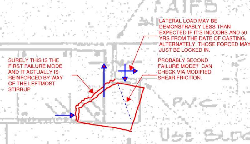
I'm also on team reinforce/replace. That said, see below for a little devilish advocation. Something that I've learned about ledges in my travels is that they are relatively insensitive to the amount of flexural reinforcing provided. Failure initiates by way of a straight shear rupture. A failure mode which, I would argue, actually is reinforced.

c01_tfsiyi.jpg
 
Scroll down this recent thread for a good visual of a “failed nib”: thread815-454584
 
From the post that Bones mentioned. It appears to be a rather shallow nib where the shear failure plane somehow ducked under the stirrups without engaging them.

c01_rtrfuy.png
 
Thanks KootK.
By further reviewing the original drawings, we found other ledge beams that actually have the typical reinforcing. Therefore, I started thinking that the engineer meant to not reinforce this ledge for some reason.
That reason, I am assuming, is that he thought he did not need to, because he checked the one-way shear and was fine, and he checked the max. tensile stress in the ledge and found it to be less that the modulus of rupture. The current Canadian Concrete standard. A23.3 allows plain concrete to be used in certain members,(ledges not included), when flexural stress doesn't exceed about 60% of the modulus of rupture.
When I checked that, assuming a vertical failure plane and adding 20% of the shear as horizontal force on the slab/ledge interface, I found the factored shear stress to be about 75% of the shear resistance, and the the max. tensile stress is about 65% of the max. allowed as noted above.
For those who want to spend some time crunching numbers, here are the parameters:
The slab grid is 20'x20'. Means, the next column line parallel to the ledge is 20' away
Thickness 8"
LL: 75 psf
overburden landscaping load 120 psf
F'c= 3000 psi
Size of the ledge is on the previously attached sketch.
I did not check my calculations for error, but irrespective of the above, we will reinforce this ledge.
 
Status
Not open for further replies.

Part and Inventory Search

Sponsor