Navigation
Install the app
How to install the app on iOS
Follow along with the video below to see how to install our site as a web app on your home screen.
Note: This feature may not be available in some browsers.
More options
You are using an out of date browser. It may not display this or other websites correctly.
You should upgrade or use an alternative browser.
You should upgrade or use an alternative browser.
Length of Plastic Hinge in steel sections 3
- Thread starter s_saranya
- Start date
- Status
- Not open for further replies.
-
1
- #2
The attached notes are from a 1964 Plastic Analysis course. Those guys took this stuff seriously back then. LOL
The distance to the location of first yield is given on the second page.
The distance to the location of first yield is given on the second page.
Thanks, similar to the stuff that Maisonette (sp) and Save had for that time period. I've used plastic design for most building type stuff (where applicable) for over 50 years. Still take it seriously.
-----*****-----
So strange to see the singularity approaching while the entire planet is rapidly turning into a hellscape. -John Coates
-Dik
-----*****-----
So strange to see the singularity approaching while the entire planet is rapidly turning into a hellscape. -John Coates
-Dik
My understanding is that it is fairly consistent, and occurs over a length approx 2x the depth (rough). It's normally used for simple continuous uniform framing where the moment is reasonably 'defined'. With this type of loading the first hinge occurs over the column (this is contained) and the second one occurs at 'mid span' (less defined). I've been aware of this but in half a century have never calculated it. If a PEMB were proportioned perfectly so that the elastic moment were exactly provided by frame... the entire structure would go into a plastic collapse at load. ![[lol] [lol] [lol]](/data/assets/smilies/lol.gif)
-----*****-----
So strange to see the singularity approaching while the entire planet is rapidly turning into a hellscape. -John Coates
-Dik
![[lol] [lol] [lol]](/data/assets/smilies/lol.gif)
-----*****-----
So strange to see the singularity approaching while the entire planet is rapidly turning into a hellscape. -John Coates
-Dik
dik said:I've used plastic design for most building type stuff (where applicable) for over 50 years. Still take it seriously.
Hey dik.
I was wanting to pick you're brain about this and was almost going to start a dedicated thread on this. I understand you use plastic design for portal frame structures. How much more efficiency do you get with plastic design over elastic design and how do you deal with deflections? What are your deflection serviceability criterium?
The reason why I ask is I currently have a 20m x 25m portal frame warehouse structure come across my desk for review. From my perspective it grossly fails conventional serviceability criteria by over 5x (but these are recommendations, no definitive criteria given). It also fails elastic design requirements by at about 3x too.
I'm pretty sure the original engineer used plastic design approaches. But I believe they flew way too close to the sun on this one, (also construction wasn't even to design either!) The entire structure is thin walled cold formed members which I can't image behave well for plastic design, I'd expect flange buckling well before the plastic limit is reached.
I've already submitted my review though since my experience with plastic design is limited, I figure I'd ask for your general thoughts.
-
1
- #7
I generally use plastic design for warehouses or plants where there is a lot of uniform continuous construction. I've not used it for large portal frames, only a few small ones. They are to provide lateral bracing in walls where X-bracing can't be used. For large portals, I would think that structures like PEMBs are more appropriate, in particular if you have a lot of them and use variable sections. Elastic design is a little more reasonable, if you can 'mimic' the BMD.
Deflections with portals can be an issue. You have to use stockier sections (generally Class 1) and, although more stocky for stiffness reasons, they are not generally suitable for deflections. You have to be careful with some PEMB structures. Manufactures in these environments occasionally use L/90 for deflections. With regular 'warehouse' type construction and continuous members. The deflection can be calculated but is normally about 1/3 of the simple span deflection. With continuous construction deflection is not normally an issue. I use normal deflection requirements whatever the structure or finishes require.
Did the original engineer use plastic design for designing the portal (realising that large portals are not normally prescribed). Are the lateral loads taken by the portal? or by roof diaphragm and X-bracing?
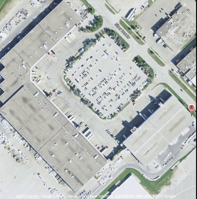
I've attached a photo of the largest plastic design structure I've done (I have no idea of how many I've completed, but dozens or more). I did both buildings. This was an unusual project that I picked up by accident. I dropped into an Arch firm to see if the project arch for Katmandu airport was back from Nepal. He wasn't so I asked if the Struct manager was available. I met him on the Cornwall Centre in Regina, which I was project engineer for. He was, so I went to lunch with him. He asked if I'd be interested in doing a project... and I said 'sure'. This was it. I ended up working for the company for about 10 years. Another interesting facit... their policy was that the dept head seal all drawings, so I had to teach Ed (manager) about plastic design.
I've not used plastic design in anything but low seismic areas, where the seismic effect is negligible. I'd have to do a lot of study for that. I don't know what the impact is.
As an aside... my design saved over 3psf in their estimated quantities and I had over 1000 budget hours left over. I have no idea of how these were arrived at. Building height for the high roof was 40' clear.
-----*****-----
So strange to see the singularity approaching while the entire planet is rapidly turning into a hellscape. -John Coates
-Dik
Deflections with portals can be an issue. You have to use stockier sections (
Did the original engineer use plastic design for designing the portal (realising that large portals are not normally prescribed). Are the lateral loads taken by the portal? or by roof diaphragm and X-bracing?
I've attached a photo of the largest plastic design structure I've done (I have no idea of how many I've completed, but dozens or more). I did both buildings. This was an unusual project that I picked up by accident. I dropped into an Arch firm to see if the project arch for Katmandu airport was back from Nepal. He wasn't so I asked if the Struct manager was available. I met him on the Cornwall Centre in Regina, which I was project engineer for. He was, so I went to lunch with him. He asked if I'd be interested in doing a project... and I said 'sure'. This was it. I ended up working for the company for about 10 years. Another interesting facit... their policy was that the dept head seal all drawings, so I had to teach Ed (manager) about plastic design.

I've not used plastic design in anything but low seismic areas, where the seismic effect is negligible. I'd have to do a lot of study for that. I don't know what the impact is.
As an aside... my design saved over 3psf in their estimated quantities and I had over 1000 budget hours left over. I have no idea of how these were arrived at. Building height for the high roof was 40' clear.
-----*****-----
So strange to see the singularity approaching while the entire planet is rapidly turning into a hellscape. -John Coates
-Dik
Thanks for the fast response Dik.
-Around here (AUS) the PEMB terminology doesn't exist though I think this construction would fit into the style of North American PEMB type construction.
-Typical lateral deflection requirements here at serviceability wind loads is h/150 for portal frames. Various authoritative sources and codes support this though there is as a recommendation but not a requirement.
-This structure has deflection of h/25. 240mm for 6m high eaves.
From what I can infer lateral loads are taken by the portals. X-bracing is minimal, extremely light (32mm x1.2mm strap) and even missing in some places (construction error). Regarding the roof diaphragm, it is generally uncommon here (at least amongst my peers and observation of construction) to consider the roof sheeting as part of the lateral restrain system. Given the amount of deflection occurring here I would expect that the roof and wall sheeting would be engaged in providing lateral restraint along the line or portals and perpendicular to them.
I do recognise that by me not including plastic analysis, nor the diaphragm effects of cladding, that some of my results are conservative. But even in light of that, this thing is so under designed that it fails regardless. Good use of plastic analysis currently isn't a part of my current skillset though this discussion has made me realise that there is one structure type that I do every second year would likely benefit from plastic analysis. (Short spans, stocky members, moment connections)
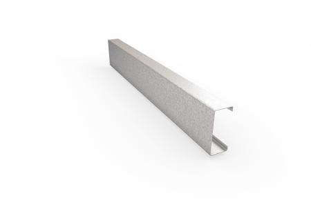
Any thoughts on using cold rolled sections in plastic design? These things are at the opposite end of class 1 sections. The main columns and rafter are 300mm deep and only 2.4mm thick to span 20m!
-Around here (AUS) the PEMB terminology doesn't exist though I think this construction would fit into the style of North American PEMB type construction.
-Typical lateral deflection requirements here at serviceability wind loads is h/150 for portal frames. Various authoritative sources and codes support this though there is as a recommendation but not a requirement.
-This structure has deflection of h/25. 240mm for 6m high eaves.
I have no idea, I can only infer. I haven't spoken to the original engineer and will likely not do so, his calculations are not available. It is a recent build, but I only have the drawings. I'm dealing with the client and the client isn't happy with what has been constructed.dik said:Did the original engineer use plastic design for designing the portal (realising that large portals are not normally prescribed). Are the lateral loads taken by the portal? or by roof diaphragm and X-bracing?
From what I can infer lateral loads are taken by the portals. X-bracing is minimal, extremely light (32mm x1.2mm strap) and even missing in some places (construction error). Regarding the roof diaphragm, it is generally uncommon here (at least amongst my peers and observation of construction) to consider the roof sheeting as part of the lateral restrain system. Given the amount of deflection occurring here I would expect that the roof and wall sheeting would be engaged in providing lateral restraint along the line or portals and perpendicular to them.
I do recognise that by me not including plastic analysis, nor the diaphragm effects of cladding, that some of my results are conservative. But even in light of that, this thing is so under designed that it fails regardless. Good use of plastic analysis currently isn't a part of my current skillset though this discussion has made me realise that there is one structure type that I do every second year would likely benefit from plastic analysis. (Short spans, stocky members, moment connections)
Any thoughts on using cold rolled sections in plastic design? These things are at the opposite end of class 1 sections. The main columns and rafter are 300mm deep and only 2.4mm thick to span 20m!

-
1
- #10
Not even after a bunch of beer... I often use a program called CUFSM for calculating the strength of CFS sections and they often go into local instability in areas of high moment. The reason plastic design uses Class 1 sections (at least in Canada) is to prevent this very thing... Plastic design requires that hinges can form and the structure can remain stable until the final hinge occurs. With plastic failure, but no collapse, the structure will remain elastic until the next load case exceeds the one that caused plastification.
-----*****-----
So strange to see the singularity approaching while the entire planet is rapidly turning into a hellscape. -John Coates
-Dik
Thanks for your helpful comments.
I will if I have time explore this further myself. At present the client has a new building that is like house built of straw.
Yeah. Our codes don't seem to be as explicit about the requirements for plastic design. For hot-rolled sections there is some requirements similar to requiring class 1 sections though possibly not as onerous. For cold-rolled I couldn't find any requirement nor any that forbid plastic design using cold rolled thin walled sections in plastic design. (Maybe because it is utter insanity.)dik said:The reason plastic design uses Class 1 sections (at least in Canada) is to prevent this very thing... Plastic design requires that hinges can form and the structure can remain stable until the final hinge occurs.
I will if I have time explore this further myself. At present the client has a new building that is like house built of straw.
The key thing in plastic design is that the section has to maintain the stability until the final 'hinge' forms... else it fails before. I've done a couple of strawbale homes... Kris Dyck, a local, is a world authority on them.
-----*****-----
So strange to see the singularity approaching while the entire planet is rapidly turning into a hellscape. -John Coates
-Dik
-----*****-----
So strange to see the singularity approaching while the entire planet is rapidly turning into a hellscape. -John Coates
-Dik
- Status
- Not open for further replies.
Similar threads
- Locked
- Question
- Replies
- 1
- Views
- 4
- Question
- Replies
- 21
- Views
- 30
- Locked
- Question
- Replies
- 2
- Views
- 5
- Locked
- Question
- Replies
- 2
- Views
- 18
- Locked
- Question
- Replies
- 10
- Views
- 15

