Continue to Site

Eng-Tips is the largest engineering community on the Internet

Intelligent Work Forums for Engineering Professionals

  • Congratulations waross on being selected by the Eng-Tips community for having the most helpful posts in the forums last week. Way to Go!

Limitations to strengthening a steel I-beam

Status
Not open for further replies.

mjr6550

Structural
Jun 27, 2006
69
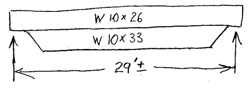
I am looking for some input from those with more experience. I seldom do much engineering with steel. I have a client who wants to remove a column in the basement of a single family dwelling. The existing beam is a W10x26. The full span is approximately 29 feet with concrete foundation walls supporting both ends. A steel column is located near the mid-span. So with the column removed the span would be doubled. Obviously the existing beam is very undersized for this condition. I discussed other options such as new columns or walls closer to the ends, but this is not acceptable.

I am looking at typical methods of strengthening the beam. Based upon preliminary engineering I was looking at welding an HSS7x4x1/2 to the bottom flange (7 being the width). I have a bit of headroom to play with, so a deeper option may be used. This gives a deflection at full DL and LL of about 1 inch. I realize that most of the time (if not all of the time) the actual LL will be less. I am a bit nervous about this much deflection because of possible effects at doorways, walls, and tile shower. I have looked at the predicted deflection at the various areas. At some areas is is not bad, but at others I have concerns. My most significant concern is that the wood 4x2 trusses at one side of the beam have two different spans with the change in span occurring near the mid-span of the beam. This will create a significant difference in deflection between two adjacent trusses.

My other concern regards whether there are practical limitations to strengthening a beam (structural or serviceability). Any input on where to terminate the new member would also be helpful (other than where is is not needed from a moment or shear? standpoint). I assume spaced and staggered welding is advisable, but should there be continuous welding at some length at each end? Also, welding across the end? Any other special considerations for HSS?

Is this something that should work or or am I asking the reinforcing to do too much? New beam may be an option, but may not be practical or cost effective.

Sorry for the long post.
 
 http://files.engineering.com/getfile.aspx?folder=3e5ea460-ec19-43c1-893f-5a29f09167e3&file=I-beam_reinforcement.pdf
Replies continue below

Recommended for you

You are right to be concerned about deflection. 1" is roughly L/360 which is generally the standard for new construction. However, you are dealing with existing construction with the loads already in place. Due to the tile construction, windows, doors, plaster cracks, etc. I'd tend to use L/600 akin to deflection in a masonry lintel. As for where to stop the reinforcing, it will depend on your moment and shear diagrams as well as deflection. As a rule of thumb, I stop reinforcing at least 2x the original member depth beyond the point where its no longer needed (20" for your W10).
 
In my area we are required to have a center post regardless of what the beam is designed to carry.
I have seen designs where deflection with no post would be limited to less than 1/480, but local code requires the post.

I would not tolerate 1" deflection, people will hate walking near the center of the house because they can feel the flex.
MC's numbers are much more realistic.

= = = = = = = = = = = = = = = = = = = =
P.E. Metallurgy, Plymouth Tube
 
I would run the reinforcement almost to the ends.
While it's not needed for moment it adds stiffness. Yes, I know that the ends of the member do not contribute that much to the stiffness but since you're already worried about deflection this is critical.
For instance, if you only put the reinforcing over 50% of the beam and wanted an accurate deflection number you'd have to analyze it as 3 section with different moment of inertia. Easy enough to do but you'll surely have greater deflection than one with the higher moment of inertia over the whole thing.

Regarding the weld, look into shear flow. That will tell you how much to weld.
No real need to weld more at the end. Welding across the flange of a stressed beam is generally considered not a good idea since it weakens the beam temporarily while it is loaded.

One option to mitigate deflection is to jack the structure a little bit before you weld the reinforcing on. This splits the deflection and reduces the impact on finishes.
So if your dead load deflection after reinforcing and removing the post will be -1", you can jack the structure +1/2" and your resultant deflection will be -1/2". Your architectural finishes will now only experience deflection ratios of +L/696 and -L/696 instead of -L/348 had you not jacked it.

Regardless, I think the structure will be really bouncy unless you really stiffen that up.
 
For welding - stitch welds staggered is fine but you DO want to weld continuously at the ends of the added shape....See AISC Section E6.

Be sure to check your bearing capacity of the wall at the ends - you are adding a lot of load to the wall supports.
Check the walls as well.

Any work you do here - whether pre-jacking the floor or not - will result in perhaps several cracks and problems upstairs due to the movement - be sure to warn the owners of this before hand.


Check out Eng-Tips Forum's Policies here:
faq731-376
 
mjr6550 said:
I have a bit of headroom to play with, so a deeper option may be used.

An HSS7x4x1/2 weighs 31.8 lb/ft and provides a composite beam with a combined depth 14". Span to Depth Ratio is 25:1 (348" / 14")

For essentially the same weight, an added W10x33 (Flange width = 8". Web & Flange thickness comparable to existing W10x26) will have significant advantages over the HSS7x4:

1. Total depth is 20", Span to Depth Ratio = 17:1. Less defection and greater stiffness (higher Moment of Inertia).

2. I have not run the numbers, but almost certainly a higher section modulus. Lower bending stress.

3. The welds are located closer to the composite beam's neutral axis. Less stress on the welds.

I would cut the ends of the added W10x33 at a 45 degree angle:

W10_Composite_Beam-1_lwjohf.png


If an added 10" depth is too much... perhaps a W8x28 or even a W6x25 instead.

[idea]
[r2d2]
 
About adding additional w10X26 parallel to the existing beam and still preserve the headroom?
 
Watch out for your install condition. You're going to have deflection and stress locked into the existing beam because of the dead load on it. That deflection will make it hard to install a single piece reinforcement (because your new piece is straight and you're trying to flush it up to a curved beam), and mean that your deflection estimates are off because you're starting with some deflection. Your stress calcs will also be off, because you have initial stresses in the existing parts of the beam.

Jack it up as much as is reasonable, and with as many support points as possible before you do this kind of work
 
how does one jack up existing bm if one is adding an additional bm to the bottom fla?...anyway, be carefull when welding if have wood nearby....TLHS makes a good point about the curvature of the existing bm....
 
29' is a long way regardless. I have W21x50's (which are significantly stiffer than what you have) in my house spanning 29' and you can feel the bounce. Granted, they do not have many walls on top to dampen things out.
Make sure you prepare them for the possibility that it could feel like a mall at times.
 
I'd look at paralleling two beams alongside the existing. It may take cutting new beam pockets at the ends or columns against the walls. Have fun getting them in. Another alternative is making a king post truss with a tie rod under the old beam. or maybe that on all three of the first sentence here.
 
I have several concerns with the proposal to reinforce the beam
1) as stated above, the end connections are now carrying much more load than previously designed for - Do you have clear understanding of the capacity of the wall connections? In concrete walls? (doubt it)
2) There was a period of time when we reinforced beams with a "beam under beam" approach. Further analysis revealed that the dramatic lowering of centroid caused the upper beam top flange to fail - this assumes a laterally Unbraced span - you did not mention if braced or not
3) if you get past braced and end connection concerns... Agreed on stitch welding another beam under. And add 20" or so continuous weld at ends
4) are you going to be able to get the 29' beam "into the basement"
5) the 10 x 33 is nice from the welder's perspective - 8" flange compared to the 26's 5-3/4" flange - means welds are in flat position -
 
Status
Not open for further replies.

Part and Inventory Search

Sponsor