Eng-Tips is the largest engineering community on the Internet

Intelligent Work Forums for Engineering Professionals

  • Congratulations waross on being selected by the Tek-Tips community for having the most helpful posts in the forums last week. Way to Go!

Liquid pressure drop across thick, multi-hole orifice plate 1

Status
Not open for further replies.

Jobst

Chemical
Mar 5, 2008
32
0
0
US
Hi All,

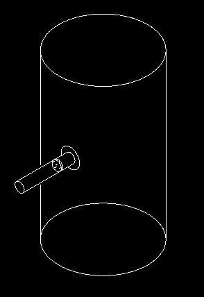
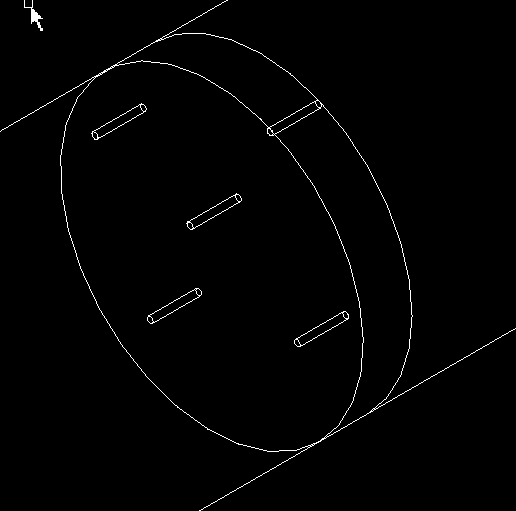
I have an issue where I'm trying to estimate the pressure drop of a liquid through a multi-hole orifice plate. I know how to do this for a "thin" plate, i.e. thickness/hole diameter <= ~1, but am having trouble finding methods for a thick plate where the aspect ratio of the holes is >>1, say in the region of 5-10. Anybody have pointers on where I might look?
 
Replies continue below

Recommended for you

Jobst,

My first question would be this: what pressure drop are you trying to calculate? Are you looking for the permanent head loss, or for the pressure loss at the tap locations for a normal tapped flange measurement?

Assuming you want permanent head loss:

McCabe, Smith, and Harriot (Chp 8) suggest that total pressure recovery from a normal orifice takes place ~ 8 pipe diameters after the orifice. This implies the vena contracta has fully expanded and normal turbulent flow is re-established by this point.

I assume that this multi-hole orifice plate is like a flow conditioner, where the holes are very small relative to the pipe diameter. If this is the case, I would suggest finding the permanent pressure loss by treating each individual orifice as a small tube with an upstream pipe that has a diameter of (Total pipe diameter)/(# of holes). Assume flow rate is (total flow)/(# of orifices). Calculate the sudden contraction and expansion pressure losses, and estimate head loss along the length of the tube. This will likely be a conservative estimate, as the sudden contraction induces a vena contracta that does not re-establish full flow for at least few pipe diameters.
 
The orifice plate is actually discharging into a pressure-controlled vessel filled with gas, so not your typical pipe flow situation. Flow through the plate is controlled, I need to make some changes to the plate and verify if the pump will still be capable of the job across the flows needed.
 
Is your application something similar to the attached images? Edit: For reference, the thickness ratio of hole diameter to plate thickness on the orifice on that sketch is 8x.

Multi-Orifice_1_wycnjt.png


Multi-Orifice_2_vyy2so.png
 
Is it a homemade plate of a bought one?
There is special software used for the flow restriction of multi-hole plates.
How good is your current flow and dP data?
Does it match with the pump curve well?
If you are modifying the plate I take it that you want more flow, correct?
Is there room that direction on the pump curve?
If you are already near BEP then you will not be able to gain much.

= = = = = = = = = = = = = = = = = = = =
P.E. Metallurgy, Plymouth Tube
 
Because the length of the orifice holes are 5x-10x their diameter, I don't see why the holes could not be treated as tubes with entrance and exit losses. As long as each tube is space sufficiently far apart that entrance effects from each hole do not significantly impact each other, it's a relatively straightforward calc. Am I missing something?
 
Hole spacing is on the order of 5-20x hole diameter. There's a bunch of plate permutations to be tested.

Flow and dP data for existing setup is ok (and close enough to what I calculate), but plate is much thinner. Correlations I'm using so far don't account for plate thickness/hole length, except via recovery term that maxes out very early, relative to the length of holes I'm talking about.

Plates are being made for us. This is an R&D application. Need to estimate dP so I can verify if existing pump will be capable of feeding new plates. If not, need to estimate dP so I can size a new pump.

TiCl4: I'll give that method a go. Might be a case of guess and check initially.
 
Sounds to me like someone should be specifying the plate for the existing pump and system. You should get that persons calcs. I'm with TiCl4 on methodology. I don't see where any guessing and checking is needed.

Good luck,
Latexman

To a ChE, the glass is always full - 1/2 air and 1/2 water
 
The suggestion of TiCl4 to treat each individual orifice as a small tuve is in the correct way.
I have designed and installed some long thick orifices (one hole) in the recirculation lines of high pressure pumps, but take into account that in your case the thick plate has several holes.
As in the case of the thin plates, the one hole plates and multi-hole plates have different flow and cavitation coefficients. Therefore the multi-hole thick orifice plates will have different coefficients as the one hole thick orifice plates.
I suggest you that look for the following paper:
"Cavitation inception and head los due to liquid flow through perforated plates of varying thickness". Journal of Fluids Engineering. March 2013. Vol.135/031302-1 - 031302-11.
 
Thanks everybody for your comments. It's been a while since I've had to do more than very standard hydraulics, appreciate the discussion.

I've set up some calculations treating the orifices as individual "pipes". The calculation has three components: entrance loss, frictional loss along the "pipe", and exit loss.
However - since the plates are discharging into a tank filled with gas (i.e. not a filled pipe or tank like a normal exit loss calc), does the exit loss need to be included? I imagine not, because the velocity of the liquid is not changing appreciably, unlike if it was discharging into a full tank where all the kinetic energy is dissipated by turbulence.
 
Jobst,

Sorry for the late reply, but you would be correct. If the orifice is truly discharging into gas space, then the exit pressure of the orifice is set by the tank pressure, and the exit loss term disappears due to the reasons you stated.
 
Status
Not open for further replies.
Back
Top