Eng-Tips is the largest engineering community on the Internet

Intelligent Work Forums for Engineering Professionals

  • Congratulations waross on being selected by the Tek-Tips community for having the most helpful posts in the forums last week. Way to Go!

Lithium Charging Load Resistance? 2

Status
Not open for further replies.

Bayview-BOOM

Mechanical
Dec 31, 2018
4
0
0
US
I'm trying to understand the load-resistance of an A123 Nanophosphate High Power Lithium Ion cell.


My understanding is that resistance increases as the cell charges.

The datasheet says "Internal Impedance (1kHz AC typical, mΩ) 8". I don't understand what that means.

Here's my (probably incorrect) attempt to apply Ohm's Law, at the low-SOC and full-SOC of the cell:

Low SOC
charging at 4A
R = V/I
R = 2.5/4
R = 0.625

High SOC
charging at 0.00001A
R = 3.7/0.00001
R = 370K
 
Replies continue below

Recommended for you

A battery is not a resistor. Why would you want to determine it's "equivalent" resistance value when charging? What purpose does that serve?
 
Is the impedance related to the I[sup]2[/sup]R losses during charging and discharging or are those losses described by a different parameter?

--------------------
Ohm's law
Not just a good idea;
It's the LAW!
 
In the Fluke document for their rather pricey battery testers (no doubt worth it to the right user) the A/C impedence is an indicator of the battery overall health regardless of charge state.
 
@3DDave: "A/C impedence is an indicator of the battery overall health regardless of charge state."

Would the tested impedance be different at different SOC?

Thx
 
If that worked you would find that being sold as a feature of battery chargers. The problem with battery degradation is that, for the same amount of charge (Coulombs) going into the cell, you get different amounts of charge available from the cell. You could have a 100% charge that is 1% of the original capacity.
 
Bayview,

The internal impedance of a battery determines its health and its short circuit capability. A battery can be modeled by an ideal voltage source in series with its internal impedance (in your case 3.3Vnom with 8 mohm). So applying a short circuit to the terminals will result in a current of 3.3/0.008 = 412A (albeit briefly!). If comparing two similar batteries of different makes, the one with the lower internal impedance will be able to supply a greater current under short circuit conditions.

The internal impedance will reduce the voltage seen at the terminal of the battery due to a V = IR voltage drop WITHIN the battery (V terminal = V ideal - I x Rint ). Of course the impedance will increase as the battery ages and that is why an old car battery struggles to start a car. The internal resistance and therefore the internal voltage drop increases, resulting in a lower terminal voltage to drive the starter motor.

I would expect the internal impedance to also vary somewhat with the state of charge. If anything though, it should decrease as the state of charge increases, which would be consistent with a higher fault current expected from a fully charged battery.

So to answer your question, your calculations for R are not correct as they do not represent the battery model.
 
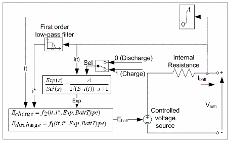
The block recommended for modeling a battery in mathworks is a more complicated version of
EnzoAus post above. Link
Screenshot_from_2023-04-05_17-11-48_xpqief.png
 
Status
Not open for further replies.
Back
Top