Continue to Site

Eng-Tips is the largest engineering community on the Internet

Intelligent Work Forums for Engineering Professionals

  • Congratulations waross on being selected by the Eng-Tips community for having the most helpful posts in the forums last week. Way to Go!

Load-Displacement Curve with ABAQUS/CAE and XFEM

Status
Not open for further replies.

dfgsdfgfd

Mechanical
Sep 30, 2015
37
Hi everyone,

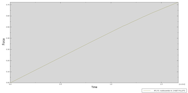
I have a notched part which I pull apart to create a crack. For the crack, I use XFEM and it works well. However, when I try to extract the load-displacement data, I only get a straight line. The crack is clearly initiated and growing, which means that the load should decrease, e.g. the line should drop and not increase further (I have displacement control). To plot the load-displacement data, I created a set of nodes on either side of the specimen which I constrained to a reference point. The right reference point is fixed, the left one moves further to the left.

Any help is greatly appreciated, thanks so much!

P.S. I also attached the .cae and .jnl files.

1_xwccwd.png

2_rzcfj5.png

3_jrdn3v.png


Replies continue below

Recommended for you

Hello,

I can not open your CAE (you are using abaqus 6.14 and I have abaqus 6.13).

If you are doing a displacement control to get Disp-Force curve you must represent Reaction Force (RF) in the reference point according the displacement.

Maybe you have forgotten to activate NLgeom in step.

 
Hello and thanks for your response and advice. Unfortunately I don't think I can save it for your Abaqus version.

I am doing a displacement control, which is why changing the representation (from Load vs. Time to Load vs. Displacement) wouldn't make a difference. The curves would still remain straight.

Nlgeom is also on.

Any other ideas, someone?
 
Hello,
The stiffness you measure does decrease. Did you expect a much larger decrease?

First of all: I don't have any experience of XFEM.

I am thinking that if you have a specimen which starts to crack, you have an effective decrease in area in a very small portion of the specimen. Even if the average strain in the smaller cross section is very large compared to the nominal strain, it is still just a very small part of the specimen.

My thinking (not 100% accurate)
Displacement d=(FL)/(AE)
Force F is constant through cross sections
Young's modulus E is constant through the cross sections
A1 = Area of cross section 1 (nominal)
A2 = Area of cross section 2 (nominal-crack)
L1 = Nominal length
L2 = Crack width
d = (F/E)*(L1/A1+L2/A2)

With some numbers:
d = (100000/205000)*(100/2000+0.00001/1500) ~ d = (100000/205000)*(100/2000)

The opposite would be to take a rubber band and stretch it. If you tie a knot on the middle, the knot will have a higher effective stiffness. That does however not change the overall stiffness of the long rubber band much.

Am I way off in my thinking? I'm just rambling on here. :D
 
Hello and thank you for the answer.

In the simulation and curve shown above (if we related it to the cross-sectional area), the stiffness increases only because the (effective) surface area decreases through the crack. However, the load continuously increases, even after onset of the crack, and during crack growth, and that's simply wrong. There should be a hump/sudden decrease in the load after the inset (after half of the specimen is cracked, less load is required to further deform it), especially since it's a very brittle material. This is simply not the case. I have both experimental data and data from another analysis where I use explicit/element deletion instead of XFEM, and both of these curves show the expected effect.

//I'm slowly starting to understand that the problem might be in the XFEM method itself, which 'overlays' a separate mesh for the crack on the actual mesh. Hence, it wouldn't be included in the output. I'm not sure if I'm on the right track, and how that would help me with the solution, but it certainly sounds feasible.
 
Status
Not open for further replies.

Part and Inventory Search

Sponsor