Eng-Tips is the largest engineering community on the Internet

Intelligent Work Forums for Engineering Professionals

  • Congratulations waross on being selected by the Tek-Tips community for having the most helpful posts in the forums last week. Way to Go!

Load Distribution Member in CFS Walls- Load Transfer to Studs.

Status
Not open for further replies.

geoffdale

Structural
Dec 17, 2004
91
0
0
CA
I am working on a project where we are designing the CFS stud walls. Studs are placed at 16" crs with owsj at 4' crs. I am checking the system using a continuous beam for the LDM and using the reactions to distribute to below studs. When the joist is bearing almost directly on the studs- I am getting little to no load sharing between the studs.
The system supplier for the floor assembly is telling me that the load distributes evenly throughout each stud but can't give me much data other than "thats how we do it". Anyone run into this before?
 
Replies continue below

Recommended for you

Will also depend on your continuous element above the stud. A CFS track is not going to have sufficient stiffness to drag load to adjacent studs.
 
I quickly made a test model in RISA with 6" CFS studs and an HSS8x4x1/4 beam. Here are the results, it appears that the load distributes pretty evenly, but that would depend entirely on the beam you are using:

2019-01-23_18_00_06-RISA-3D_-_C__Users_User_Documents_RISA_Model_Files_untitled.r3d_whkisu.png
 
The cold-formed steel engineers institute has some pretty good technical information on load distribution members. Below are a couple of links:

Research Study Using Tube Steel Distribution Headers (See page 4 of the .pdf)

Technical bulletin calculating top track load distribution members.

The values in first article seems like it may substantiate some of the floor assembly suppliers claims.
 
I think it is impossible to correctly model this situation. Lets face it, studs are never cut exactly the same length, they are never always tight in the track etc. This leads to alot of opportunity for localized compliance at each stud. I usually just design the HSS member for something on the order of less than 1/16" of deflection and call it a day. The wall will figure the rest out.
 
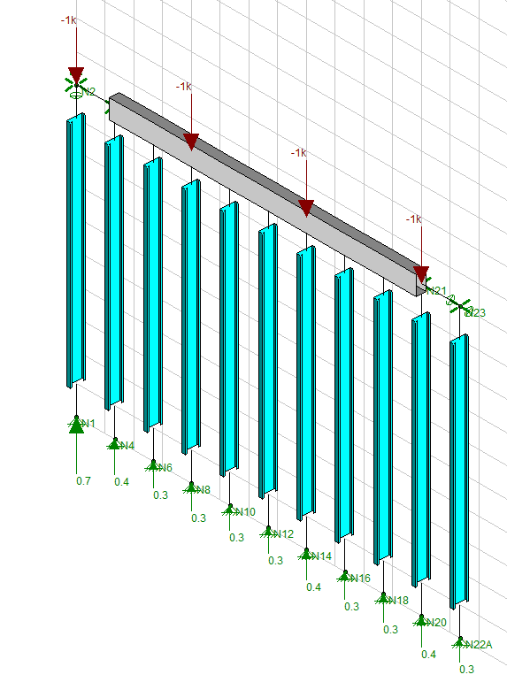
The model by bhiggins is a good example of how a minor change in the "system" can make a big difference. Note the left stud has a .7 reaction while the right stud has .3 reaction. The left stud has a load right over the end stud that has no stud to share to on one side and the top member is not fixed at that location. The right stud has the load a few feet away. A similar thing could occur at every "joint" in the top member unless the top member joints are moment connected versus shear connected.

I do not do much CFS design anymore, but as I recall, the track lengths are not very long. The stiffness of the top member is one of the main factors, but so is how they are joined to each other. Very minor differences in load sharing can be accounted for in the Factor of Safety but not a .7/.3 = 2.33 difference. I do not know how much lapping is done on the top member, but if I was relying on load sharing to occur, I would have a good lap length and maybe double studs at the end of a run. Run the model as a solid length and then also with shear only joints in it.

XR205's comment is another thing that affects isolated studs. Joist pushes on track, track attempts to close any gap in it and the stud via bearing of the screws. Put 2 screws per side on one stud and 1 screw on another stud and you get another minor change assuming they both have the same gap. And along the same lines as XR250 said, the floor is not flat. One stud over a track that is 1/16" off the floor while the track under the stud on each side is hard against the floor.

While there is some load sharing going on and since we are talking about repetitive members, I would not value the load sharing as simple as the supplier does but I would consider it to be significant within some boundaries.

 
When you do your computer model, put DL on everything and "scatter out" your LL. For example, put none one location, full on the next location and none on the next at one time. My guess is that most of the LL in the loaded one is going into the stud below it. In the consistently loaded model, a pair of 1k loads are "pulling" the LDM down onto the studs in between them. If you disrupt the consistency, they will not be "pulling" the LDM down onto the unloaded studs as much. LL application is not as reliable as to when and how it occurs. This is more of a factor in high LL and low DL than high DL and low LL.

I mention this since your oswj spacing is 4'. Wider spacings tend to cause this to me more likely to occur.
 
Status
Not open for further replies.
Back
Top