Studentforlife
Aerospace
- Aug 28, 2020
- 11
Hello all,
I hope that all my fellow engineers are keeping well and safe. I was looking to get some advice from well-seasoned aircraft stress engineers on this forum.
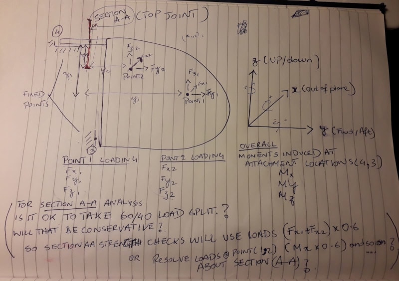
I have recently come across a problem where I have loads defined for points 1,2 and combined moments at the location where the structure is fixed (points 3,4). I hope you can see the picture which I have tried to attach. I am now assessing Section a-a of the structure for stability and strength (by calculating section properties: moment of inertia, neutral axis etc.).
Would it be acceptable or conservative if I took a 60/40 load and moment split to obtain the loads at Section A-A? So the loading will look something like (Fx1+Fx2)x0.6, (Fy1+Fy2)*0.6 ... Mx x (0.6), My x(0.6) and so on?
Or
Do you suggest I resolve loads from Points 1 and Point 2 onto the neutral axis and obtain loads of Section a-a that way? Please keep in mind that the structure is fixed at points 3,4.
What are your thoughts? Looking forward to hearing from you.
Many Thanks
Regards,
Sam
I hope that all my fellow engineers are keeping well and safe. I was looking to get some advice from well-seasoned aircraft stress engineers on this forum.
I have recently come across a problem where I have loads defined for points 1,2 and combined moments at the location where the structure is fixed (points 3,4). I hope you can see the picture which I have tried to attach. I am now assessing Section a-a of the structure for stability and strength (by calculating section properties: moment of inertia, neutral axis etc.).
Would it be acceptable or conservative if I took a 60/40 load and moment split to obtain the loads at Section A-A? So the loading will look something like (Fx1+Fx2)x0.6, (Fy1+Fy2)*0.6 ... Mx x (0.6), My x(0.6) and so on?
Or
Do you suggest I resolve loads from Points 1 and Point 2 onto the neutral axis and obtain loads of Section a-a that way? Please keep in mind that the structure is fixed at points 3,4.
What are your thoughts? Looking forward to hearing from you.
Many Thanks
Regards,
Sam