Continue to Site

Eng-Tips is the largest engineering community on the Internet

Intelligent Work Forums for Engineering Professionals

  • Congratulations GregLocock on being selected by the Eng-Tips community for having the most helpful posts in the forums last week. Way to Go!

Loads on arches truss supporting water piping 3

Status
Not open for further replies.

Italo01

Structural
Sep 4, 2021
169
Hello,

I was hired by a water supplier company to design a arched truss that will support a water pipe over a river. The truss will span 50 meters.

For the design lodas, i'm considering the pipe, water and structure weights, Wind and hydraulic thrust, but some maintenance workers will eventually go over the structure. The company didn't provide this additional load and i cannot found anything similar in the brazilian codes.

Does anyone knows a code provision of some country for a structure like this?

Thank you.
 
 https://files.engineering.com/getfile.aspx?folder=04fe17af-8f14-4e77-86c0-4cb2b2d8dd7d&file=Screenshot_20220810-115245_Drive.jpg
Replies continue below

Recommended for you

PS: The drawing was given by the company only for illustrative purposes.
 
Don't think you'll find this in any "code" as it is a restricted access bridge in effect.

Just assume 4 100kg blokes at the centre point as a live load and add some signs on the structure saying no more than xx persons allowed on the structure at any one time. Can't think it's going to make any real impact though as the lateral wind loads are probably your defining load.

They are nice pipe bridges though.

Remember - More details = better answers
Also: If you get a response it's polite to respond to it.
 
Thanks LittleInch.

You are correct, the wind loads are critical and the live load that i considered(34plf, balanced and unbalanced) had little influence on the design.

 
This is one over a canal somewhere.

pbridge_bogncx.jpg


Remember - More details = better answers
Also: If you get a response it's polite to respond to it.
 
The live-loading due to workers is somewhat up to you, but you should get buy-in from the owner. What kind of work will be done up there? Unlike a conveyor, I can't see the workers bringing very heavy tools/replacement parts for piping. But I could be wrong.

Our of curiosity, if there is an issue with one of the pipes on the bridge and it needs to be replaced, how will the owner approach it? The answer to that will probably drive your live load due to workers.

Please note that is a "v" (as in Violin) not a "y".
 
You would have to scaffold the whole thing out to any serious cutting and welding, so nothing more than a portable grinder and a paint brush.

And get a big crane.

But those sorts of bridges are basically good for 50 years if you build it right.

Remember - More details = better answers
Also: If you get a response it's polite to respond to it.
 
I wonder why they have a pin joint on the CL ? Maybe erect it with a pin joint, then go and add a "proper" fixed joint ??

"Hoffen wir mal, dass alles gut geht !"
General Paulus, Nov 1942, outside Stalingrad after the launch of Operation Uranus.
 
rb1957,

It's just a 3-pin arch. IIRC, it makes it easy to analyze and construct. I'm sure one of the older members could wax eloquently about it as a structural system.

Please note that is a "v" (as in Violin) not a "y".
 
The schematic drawing is not depicting a box truss, but rather a U-shaped structure. Be careful about the buckling of such a structure. I would make it a box and add separate, non-structural guardrail for the walkway. (And use 40 psf LL on the walkway).
 
JLNJ (Structural) said:
The schematic drawing is not depicting a box truss, but rather a U-shaped structure. Be careful about the buckling of such a structure. I would make it a box and add separate, non-structural guardrail for the walkway. (And use 40 psf LL on the walkway).

Come on, JLNJ, you've never used Engesser's solution for a half-through pony truss, and detailed a moment connection b/w the side verticals and the beam/strut underneath?

LittleInch (Petroleum) said:
HUGE concrete blocks at each end though

Well yes, it's a 3-pin structure, not 2-pins and a roller. :)

Please note that is a "v" (as in Violin) not a "y".
 
"I'm sure one of the older members could wax eloquently about it as a structural system." ... please, don't encourage them !?

"Hoffen wir mal, dass alles gut geht !"
General Paulus, Nov 1942, outside Stalingrad after the launch of Operation Uranus.
 
Thanks guys for the inputs.

JLNJ, i already changed to a box structure to improve torsion stiffness and increased the spacing between between the arches to increase out-of-plane stiffness. Thank you for your suggestions.
 
I don't know if i should create a new thread for this question, but does anyone have some detailing tips for inclined columns(Or truss chords in this case)?

One of the things that i would like some inputs is about tolerances. The shear load on the base plates is pretty high, and since it's subject to tension, i'm relying on the anchor rods to resist the shear. Two anchor rods are not enough to resist shear so i'm counting on all of them and AISC's Design Guide 01 states:

"

The authors recommend a cautious approach, such as using only two of the anchor rods to transfer the shear, unless special provisions are made to equalize the load to all anchor rods . Lateral forces can be transferred equally to all anchor rods, or to selective anchor rods, by using a plate washer welded to the base plate between the anchor rod nut and the top of the base plate. The plate washers should have holes 1/16in. larger than the anchor rod diameter. Alternatively, to transfer the shear equally to all anchor rods, a setting plate of proper thickness can be used and then field welded to the base plate after the column is erected. It cannot be emphasized enough that the use of shear in the anchor rods requires attention in the design process to the construction issues associated with column bases.


"

I thought of using the wahser plates but maybe the 1/16in will be a problem due to a potential settling of the anchor rods.
 
Italo01 said:
I don't know if i should create a new thread for this question, but does anyone have some detailing tips for inclined columns(Or truss chords in this case)?

One of the things that i would like some inputs is about tolerances. The shear load on the base plates is pretty high, and since it's subject to tension, i'm relying on the anchor rods to resist the shear. Two anchor rods are not enough to resist shear so i'm counting on all of them and AISC's Design Guide 01 states:

One thread is best. Then we don't have to hop from thread to thread.

The shear load should not be too high if you use sloping anchorages as suggested in your first sketch, at least not from gravity load. There will be a wind shear, but it should be of tolerable magnitude.

Torsion and bending from wind forces is a bit tricky. That will take a bit of thought.

Are you considering shapes other than a circular arch?


BA
 
Yes, The shear is primarily from wind on transverse direction. The torsion will also be resolved into shear on the 4 supports in each side.

I considered a catenary shape, since the primary load is the pipe and water wheight, which follow the structure curve, and the catenary is the ideal shape for an arch under its own weight.
 
A circular shape would be simpler to detail and fabricate.
 
Your suggestion was great. I did redo my analysis with a circular shape and the structure is almost as efficient as the catenary and the detailling will be much easier. Thanks JStephen.
 
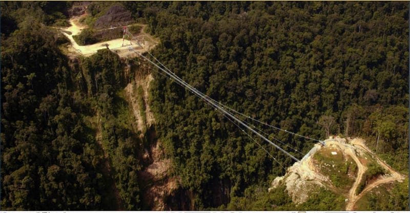
A cable suspended pipe would be a very economical solution, and it handles wind forces easily.

Capture_mgv3sm.jpg


BA
 
Status
Not open for further replies.

Part and Inventory Search

Sponsor