Eng-Tips is the largest engineering community on the Internet

Intelligent Work Forums for Engineering Professionals

  • Congratulations waross on being selected by the Tek-Tips community for having the most helpful posts in the forums last week. Way to Go!

Local Mesh Refinement and Mesh Convergence under Solid Surface 1

Status
Not open for further replies.

MegaStructures

Structural
Sep 26, 2019
366
0
0
US
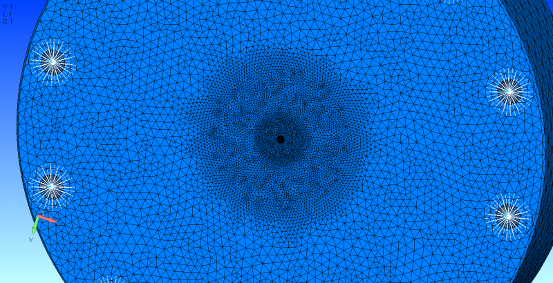
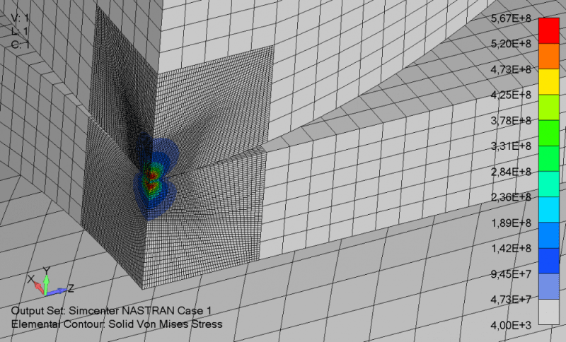
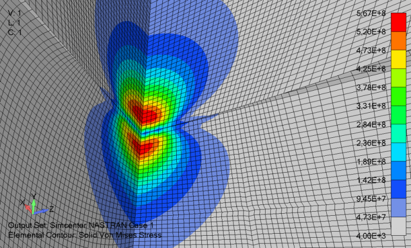
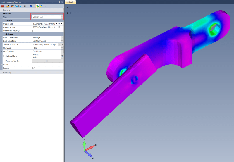
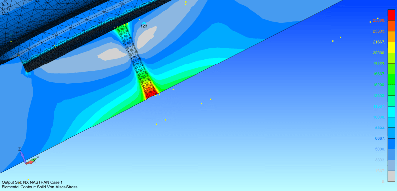
I am reading through a paper on mesh convergence created by ANSYS and they have pointed out something I have long wondered about FEMAP's solid refinement method using mesh by surface on the meshing toolbox. The basic claim by ANSYS is even though the surface mesh has been refined on a solid there can still be larger poorly shaped elements laying just under the surface that can cause errors in mesh discretization. I have worried about this is in FEMAP and have often figured out ways avoid using TET mesh and local refinement techniques and instead use a uniformly refined HEX mesh where possible, so I know exactly what type of element I am getting through the cross-section. However, sometimes this is not possible with complex geometry and I must mesh the piece with TET elements and due to computing power and time, I must refine locally near high-stress gradient regions. Can anyone help me understand if this is a real concern and if there are techniques I can use to avoid any errors caused by this if so?

ANSYS quote: "they appear graphically equal and the criteria from 1A and 1B have been met. However, convergence must be verified graphically. Figure 5 shows a plot of the convergence from the table above. Note that the curve has not visually flattened out and that there is still a 21% error between the final average value of 124,099PSI and the previous hand calculations of 156,849PSI. Note that this method of meshing and iteration resulted in no mesh quality errors or warnings and met our main accuracy criteria, yet an error still exists in the model. This method of meshing was performed to illustrate a point. Often in a solid mesh there can exist very poorly shaped elements just below the surface although the number of elements along the surface appear adequate to ensure an accurate solution"

 
Replies continue below

Recommended for you

@karachun sure!

When meshing the below part I meshed the entire part to 0.5" using Mesh--> Geometry --> Solids. Then after the first iteration I noticed a large stress gradient near a small hole in the middle of the part, so instead of refining the mesh globally using the same command before I went to the meshing toolbar and refined the mesh by surface right around the stress gradient. This took two additional iterations before I got the mesh to converge. On the surface everything looks great; however, when refining a solid mesh by surface I have no idea what is going on through the cross section of the part. What's to say that the mesh is converged for any of the elements not on the immediate surface if that makes any sense.
 
Almost forgot the image. Also I realize I absolutely killed this piece with tiny TET elements, but my stress concentration was much smaller than the overall piece. I suppose that's a topic for a whole different conversation.

mesh_convergence_at_surface_nbplxv.png
 
If you are concerned about the cross section you can use the Section Cut to view the contours of elements within the solid. If you see any peak stress in an area that isn't around a feature check to element quality in that area. If the quality is bad it might be an artificial peak.

Normal:
nonSectionCut_l0vfky.png


Section Cut:
SectionCut_bqumww.png
 
Ah, great trick TG. I was using the section cut in the view settings, which doesn't show solids through the section. Too bad the contour doesn't show filled edges in the middle, but at least it shows if there is a smooth stress gradient.

Karachun, I did think about doing that for this part, but I could see that being tedious to cut out and glue stress concentration regions in every model. By your suggestion to slice the region and "globally" remesh the slice are you saying you agree that it is a problem to refine the mesh by surface?

Section_Cut_ec2dgj.png
 
If you use tet mesh then yes, you can refine mesh on curve/surface. My motto is "hexa mesh or nothing", I use structured hexa mesh where it is possible, because hexa mesh is accurate, light and neat.

MegaStructures said:
but I could see that being tedious to cut out and glue stress concentration regions in every model
Satisfaction from neat structural hexahedral mesh is worth it.

P.S. Use only tet mesh with midside nodes!!!
 
That is definitely a beautiful mesh and I too prefer to use a HEX mesh wherever possible. I’ve always been a little hesitant to overuse glued connections, because I don’t understand how it isn’t adding stiffness to the stiffness matrix. From my best understanding of glued connections what FEMAP is doing to glue surfaces is connecting nodes at glued surfaces with rigid connectors I.e. perfectly transferring translations and moments from node to node.

The rest of my part not shown here has some nasty geometry that would take days to prepare for a hex mesh, so I would embed the surface around the stress concentration shown and HEX mesh it, but undoubtedly there’s not going to be a great match between the nodes on the HEX meshed surface and the TET meshed surface. How big of a concern is that? It seems to me that the farther these rigid elements have to “reach” from node to node the more inaccurate the displacement results become.

All this to say it would be far easier to be able to TET mesh this part and refine locally near stress gradients, which FEMAP obviously offers the capability to do, but I just don’t have a good idea of what is going on under the surface and want to figure out if I should be concerned about using this work flow.
 
Status
Not open for further replies.
Back
Top