Ivan Silva
Industrial
Hello,
I'm solving some question about position tolerance from a book and there are two of them which I didn't understand what is wrong with my resolution. Could someone help me with it?
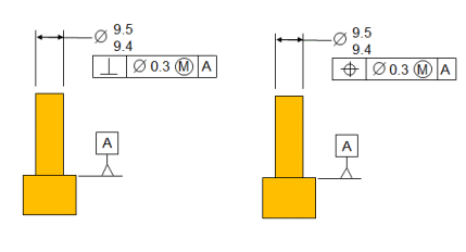
Picture for question 69 and 70:

69. The perpendicularity callout and this tolerance of position callout:
A. Have exactly the same meaning (official answer)
B. Have a different meaning
My resolution:
The perpendicularity tolerance tells that the cylidrical face must fit inside an 9.8 diameter cylinder which is perpendicular to datum A.
The position tolerance tells that the uAME axis must fit inside an variable diameter cylinder (it's variable because bonus tolerance is allowed
This said, I don't understand why both tolerance have the same meaning since one control a face inside a fixed diameter cylinder and another a axis inside a variable diameter cylinder.
-----------------------------------------------------------------------------------------------------------------------------------
70. It’s legal to use the tolerance of position callout solely to control perpendicularity:
A. True (official answer)
B. False
Is not the position tolerance knowed as a tolerance which controls position and orientation at the same time? Is there a way to cancel the position control of an position tolerance?
PS: I'm studying GD&T by myself trough the standard and some books. So I don't have any teacher guiding me who could solve the exercises.
I'm solving some question about position tolerance from a book and there are two of them which I didn't understand what is wrong with my resolution. Could someone help me with it?
Picture for question 69 and 70:

69. The perpendicularity callout and this tolerance of position callout:
A. Have exactly the same meaning (official answer)
B. Have a different meaning
My resolution:
The perpendicularity tolerance tells that the cylidrical face must fit inside an 9.8 diameter cylinder which is perpendicular to datum A.
The position tolerance tells that the uAME axis must fit inside an variable diameter cylinder (it's variable because bonus tolerance is allowed
This said, I don't understand why both tolerance have the same meaning since one control a face inside a fixed diameter cylinder and another a axis inside a variable diameter cylinder.
-----------------------------------------------------------------------------------------------------------------------------------
70. It’s legal to use the tolerance of position callout solely to control perpendicularity:
A. True (official answer)
B. False
Is not the position tolerance knowed as a tolerance which controls position and orientation at the same time? Is there a way to cancel the position control of an position tolerance?
PS: I'm studying GD&T by myself trough the standard and some books. So I don't have any teacher guiding me who could solve the exercises.
