Eng-Tips is the largest engineering community on the Internet

Intelligent Work Forums for Engineering Professionals

  • Congratulations waross on being selected by the Tek-Tips community for having the most helpful posts in the forums last week. Way to Go!

Location Tolerance for ID or OD Acting as Secondary Datum Feature

Status
Not open for further replies.

Peter the Engineer

Mechanical
May 7, 2021
4
0
0
US
Hi, I am fairly new to GD&T and still learning from the 2009 GD&T standard book. I noticed that if an ID or OD is used as a secondary datum feature, it is usually not given a location tolerance. Only perpendicularity tolerance is used.
4-9_zfcst3.jpg
4-15_w8msii.jpg

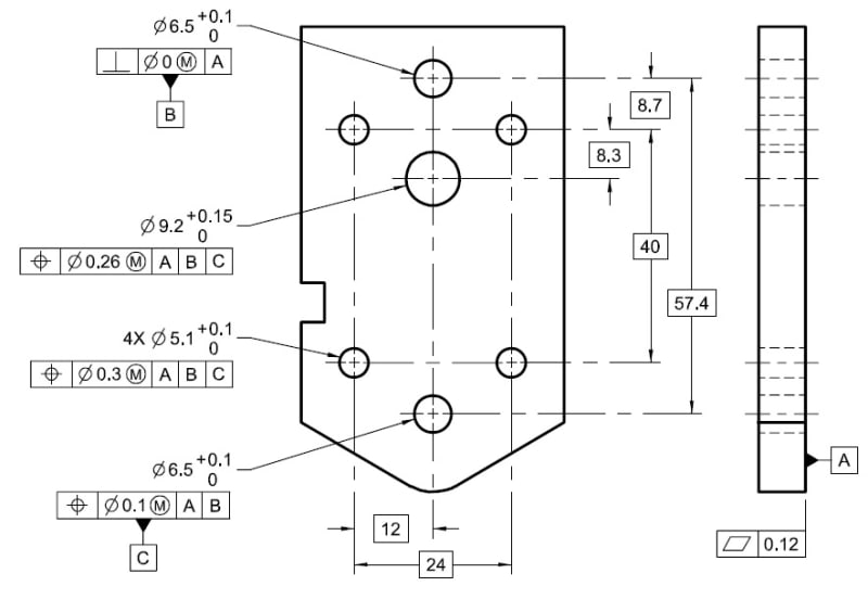
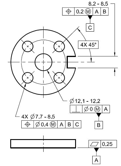
Fig 4-9 and 4-15 from the standard illustrate this. The secondary datum features are only given perpendicularity controls. That being said, are we not controlling the position of these secondary datum features? Are we saying that these secondary datum features are free to float anywhere, just as long as other features that are dependent on them are located based on their actual locations? I am always under the impression that for any given feature, we have to control the location, orientation, form, and size. Thanks masters!
 
Replies continue below

Recommended for you

Are we saying that these secondary datum features are free to float anywhere, just as long as other features that are dependent on them are located based on their actual locations?
That's right... that secondary datum feature could be off by a mile and you'd never know it, because everything else on the part will follow that hole (and other datums as referenced).

I am always under the impression that for any given feature, we have to control the location, orientation, form, and size.
Not necessarily -- only control what is needed for complete definition and function.
 
Peter the Engineer,

If my secondary datum feature is a hole, it is correct by definition, i.e. it is correct because I damn well say it is. Everything else is located from the hole.

--
JHG
 
The FCFs form a linked list of dependencies. Datum feature B has only a single link, to datum feature A and only a single degree of freedom, perpendicularity. However, it's not because it is used as a secondary reference in other feature control frames.

In the case of mounting holes for a panel meter, the large hole is likely to be used as the secondary datum feature for the fastener holes, but the large hole will certainly have a location tolerance zone relative to other datum features.

See figure 7-37, Multiple Patterns of Features.
 
3DDave said:
Datum feature B has only a single link, to datum feature A and only a single degree of freedom, perpendicularity.

Perpendicularity is actually two degrees of freedom.

John Acosta, GDTP Senior Level
Manufacturing Engineering Tech
 
It controls only one angle.

The geometry of the hole constrains two translation degrees of freedom, the perpendicularity requirement limits only one orientation degree of freedom.
 
Wow thank you all so much! I wish I had known this forum earlier. I'm a rather slow learner, and it takes me 1.5 hours in average to understand a single page in the 2009 standard book.
 
Dave,

In the interest of learning, not being argumentative, I'd like to pursue this a little. As I understand perpendicularity, it constrains two rotations, thus actually two angles. If an axis is to be perpendicular to a datum--let's say the simulator is the granite plate of a CMM--then we are controlling the orientation of the axis along the XZ plane and along the YZ plane. That's two degrees of freedom being constrained. In this case we are constraining u and v. I've always considered perpendicularity a characteristic, not a degree of freedom. I'm not sure where I got that notion from though.

John Acosta, GDTP Senior Level
Manufacturing Engineering Tech
 
Hi Guys I am a little confused with these drawings, and I not here to contest the constraints or what ever. I believe what ever as discussed.
question was asked why were the outer configurations not dimensioned on these drawings and that means it could be what ever.
and according to these drawings this is true.

first of all to me it would be have to unspecified dimension some where in the notes.
secondly I look at the true position of the holes. there is no edge distance dimension.
to me these drawings are incorrect. and not dimensioned properly.

look at the position tolerance of the holes very tight, and maybe that's not the discussion here
but in order to hold these tight of tolerance the datums have to be even tighter.
the flatness is given .12 flatness tolerance, but in reality it must be better than .05
looking at these drawings the holes would require jig grinding and both sides would require surface grinding
prior to jig grinding. just making rhetorical question.
just pointing out the dimensioning will effect more expensive operations and inspection. means more $$$.
 
Original observation:

OP said:
I noticed that if an ID or OD is used as a secondary datum feature, it is usually not given a location tolerance. Only perpendicularity tolerance is used.

As is typical in these standards the examples leave off many of the dimensions required to fully describe a part. It's distracting that they do this when simply making the uncontrolled portions phantom would focus on what they want, but given the generally poor layout of the document (splitting paragraphs with, if memory serves, up to 8 pages of diagrams,) I don't expect better.

The datum feature controls appear fairly tight; in the upper diagram, 0.12 over at least 24mm (eyeballing, more like 30mm) vs upto 0.10 over (eyeballing) 10mm, so the allowance for datum feature A variation is half as large as that allowed for datum feature B. 0.10/10 => 0.57 degrees, a noticeable error on most machining operations. I suppose 0.004 inches could be improved on but I would not anticipate a noticeable rocking, nor enough distortion from clamping to create or remove more than 0.5 degrees in the orientation of datum feature B.
 
mfgenggear,

Any datum references in a feature control frame are always with respect to datums, not datum features. I don't see a problem with a 0.12 flatness tolerance on datum feature A and the position tolerances with respect to datum A. Whether or not the tolerance values are too loose or too tight is another thing. Considering that the part is completely made up, we have no information to go on to tell us one way or the other.

John Acosta, GDTP Senior Level
Manufacturing Engineering Tech
 
mfgenggear said:
these are junk drawings and are bad examples for teaching newbies.

Many are certainly incomplete. No argument there. That still doesn't mean the tolerances are too tight or too loose in the above drawing. Also, the standard is not a textbook. It purpose is not to teach GD&T. Instead, think of the standard as a rule book. It establishes the rules for applying GD&T. If you want to learn GD&T, get a coach. I doubt anyone ever learned how to play football strictly by reading the rule book.

John Acosta, GDTP Senior Level
Manufacturing Engineering Tech
 
Status
Not open for further replies.
Back
Top