Continue to Site

Eng-Tips is the largest engineering community on the Internet

Intelligent Work Forums for Engineering Professionals

  • Congratulations KootK on being selected by the Eng-Tips community for having the most helpful posts in the forums last week. Way to Go!

longitudinal shear between precast wall/ core

Status
Not open for further replies.

4dmodeller

Structural
Oct 8, 2015
39
Hi all,

I am aware that we can use VQ/I to design for longitudinal shear in a planar wall/ 3D wall.

However, my question is if there is torsion in the shear core, how do you break down torsional force back into shear force for design? it makes sense if it's a closed box (T*/2Ao).
However, most shear core has door/ lift opening or is an open section. Some research of open section shear flow due to torsion does not show how I can workout longitudinal shear through precast vertical joint.
does anyone have any idea?

One possible method i found is:
Let say I use ETABS as a structural analysis tool
I did a bit of digging in eng tips forum and found some member suggested to look at the shear in each leg separately by assigning each wall leg as an individual pier for shear check..and entire core as one pier for flexural/ axial check. this way torsional shear is broken down into each leg for you by the program.
My question is then..if you know the V* force acting on that particular panel, how do you work out the longitudinal shear requirement? you can't use VQ/I anymore as it is part of the box (you would need V* of entire box otherwise)
Some more digging suggested V*H/L to work out longitudinal shear requirement...however, beside stability point of view (I assumed this is how the V*H/L is derived).. i don't see how it's equivalent to VQ/I--where longitudinal shear connection at mid length would be higher than if the joint is close to the edge.

Can anyone help me on this one?
 
Replies continue below

Recommended for you

Open section shaft walls will resist torque primarily through warping torsion. If you google the works by Bungale Taranath, Alexander Coull, and Bryan Stafford, you'll find a wealth of information. It's complex stuff however. Sectorial coordinates and all that jazz.

If you've performed a 3D analysis that would capture warping torsion effects then you should see the longitudinal shear demand in the walls due to torsion showing up as a vertical shear loads on your individual wall panels. If so, that's the force that you can design to. To some degree, it also depends on your foundation modelling. If your walls are rigidly attached to a rigid foundation, that will affect things.

I like to debate structural engineering theory -- a lot. If I challenge you on something, know that I'm doing so because I respect your opinion enough to either change it or adopt it.
 
Kootk in which company do u work ? they are really lucky to have you
 
chekre said:
KootK in which company do u work ?

KootK prefers to lurk in anonymity.

chekre said:
they are really lucky to have you

That's very kind of you to say -- thank you. Don't be so sure about my employer's good fortune however. My penchant for technical rigor has a tendency to slow down production work. I'm a manager of sorts these days so I try to keep my tech-nose out of other peoples business as much as possible. It's tough though as I really miss hands on design. That's partly why I hang out here and stick my tech-nose into the business of random, internet structural engineers!

I like to debate structural engineering theory -- a lot. If I challenge you on something, know that I'm doing so because I respect your opinion enough to either change it or adopt it.
 
Kootk,

Can you recommend the name of the book instead of author?
KootK said:
warping torsion effects then you should see the longitudinal shear demand in the walls due to torsion showing up as a vertical shear loads on your individual wall panels.

I am not sure how to work out longitudinal/ vertical shear in etabs..except to label individual wall as spandrel and use V3 output? is that what you are referring to?, pier output only reports shear demand at top and bottom of pier. are you familiar with etabs?

KootK said:
To some degree, it also depends on your foundation modelling. If your walls are rigidly attached to a rigid foundation, that will affect things.

I think you are referring to the fact that warping tend to occur near rigid support where there is warping restraint, and free torsion more up top of building?? is that what you mean?
i just model each wall support as pin support (no drawings of pile caps etc.) i dont know if that is considered as rigid foundation
 
As far as i know, etabs 9.7 didnt include in its reinforcement the torsional bars.
Regarding the new etabs veraion 15, i will check tomorrow if the torsional reinforcement has been included for wall element.
 
4D said:
Can you recommend the name of the book instead of author?

Link, Link, and a bunch of research papers.

4D said:
I am not sure how to work out longitudinal/ vertical shear in etabs..except to label individual wall as spandrel and use V3 output? is that what you are referring to?, pier output only reports shear demand at top and bottom of pier. are you familiar with etabs?

I'm not familiar enough with it that I can speak in terms of V1/M3/R2 etc. One way or another, the longitudinal shear forces connecting the individual wall panels of the composite shape must manifest themselves as vertical shear forces on the individual panels.

4D said:
I think you are referring to the fact that warping tend to occur near rigid support where there is warping restraint, and free torsion more up top of building?? is that what you mean?

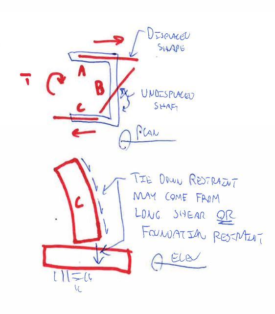
A shear wall is a vertical cantilever with some degree of warping restraint provided at the foundation. If that restraint is small, then the longitudinal shear demand on the wall joints will be larger. If that restraint is large, then the longitudinal shear demand on the wall joints will be smaller. See the sketch below.

4D said:
just model each wall support as pin support (no drawings of pile caps etc.) i dont know if that is considered as rigid foundation

That is considered a rigid foundation and is what most folks do most of the time in my experience.

Capture1_w0d0xj.jpg


I like to debate structural engineering theory -- a lot. If I challenge you on something, know that I'm doing so because I respect your opinion enough to either change it or adopt it.
 
Chekre, I dont use etabs for design. i only use it for load output.

KootK said:
A shear wall is a vertical cantilever with some degree of warping restraint provided at the foundation. If that restraint is small, then the longitudinal shear demand on the wall joints will be larger. If that restraint is large, then the longitudinal shear demand on the wall joints will be smaller. See the sketch below.

Are you saying that the foundation takes some of the warping torsion away from the core, thus less torsion left in the core and thus, less longitudinal shear is demanded in the shear wall?

This still does not help me work out how i can establish how much additional shear is created due to torsion...and in fact i believe warping torsion increases longitudinal stress demand...doesn't this mean i have to add torsion axial load to P/A +M/Zx+M/Zy....oh this is getting too complicated..how would you do that!~
 
4d said:
Are you saying that the foundation takes some of the warping torsion away from the core, thus less torsion left in the core and thus, less longitudinal shear is demanded in the shear wall?

Close. The torsion in the cores should remain more or less unchanged. However, the foundation will limit the amount of torsional warping deformation experienced by the core.

4d said:
.and in fact i believe warping torsion increases longitudinal stress demand.

I agree. However, I also believe that the effect is quite modest in most cases.

4d said:
oh this is getting too complicated..how would you do that!~

You could approximate it by hand but, given that you've already got a model up and running in ETABS, it will surely be more efficient to let ETABS do the work for you. Try this:

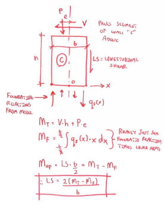
1) Each individual wall panel (shaft side) will have a total overturning moment (M_t) induced in it by the applied shear and axial loads. You should be able to extract this from your model.
2) Part of the overturning moment will be resisted by the foundation reactions (M_f). You should be able to extract this from your model.
3) Part of the overturning moment will be resisted by the shear connection to the adjoining panels (M_ap). If M_ap cannot be extracted directly from your model, calculate it as M_ap = M_t - M_f.
4) Use M_ap to work out the longitudinal shear demand at the panel joint. This value will include the requirement for shear transfer due to both flexure and torsion.

I like to debate structural engineering theory -- a lot. If I challenge you on something, know that I'm doing so because I respect your opinion enough to either change it or adopt it.
 
KootK,

I don't think etabs can separate the load into M_t and M-f...or I still don't understand what they mean...M_t is created by shear and axial? im guessing that's the load from the diaphragm and gravity load..
I don't get M_f...resisting force (M_t) vs. overturning force (M-F)..im not sure i understand.

I have attached the model here..if anyone can help that would be great.
 
 http://files.engineering.com/getfile.aspx?folder=959afecc-f68c-42a2-a5d4-48eccc768bfb&file=model.EDB
4D said:
I don't get M_f...resisting force (M_t) vs. overturning force (M-F)..im not sure i understand.

Yeah, it was probably a little optimistic/lazy of me to think that we could get by without a sketch here. My bad. Check out the sketch included below. It's really just equilibrium on the panel.

4D said:
M_t is created by shear and axial? im guessing that's the load from the diaphragm and gravity load..

Precisely.

Capture_zc1tia.jpg


I like to debate structural engineering theory -- a lot. If I challenge you on something, know that I'm doing so because I respect your opinion enough to either change it or adopt it.
 
KootK,

That is almost exactly what I was suggested by someone i knew..however, i lost contact with him so I can't ask him anymore...please find attached screenshot of what I was explained....
my question is that this method doesn't explain why panel closer to the center of long panel is experiencing for longitudinal shear..can you explain how?

also, what if you have a series of panel...the model you suggested doesnt include contribution of longitudinal shear resistance created by a panel on the left ...of the panel you drew..for example...wouldn't that help stabilize the panel?


can this approach help explain a staggered precant panel joint (looks like a key joint where no stitch plate is usually required)i.e. Longitudinal shear is resisted by the panel below that particular panel...and effectively, each panel resists double the amount of longitudinal shear (one of itself and one of the panel above)


 http://files.engineering.com/getfile.aspx?folder=6aa93929-e2b6-4074-8f7a-d4d0bfb20d92&file=pic.png
4d said:
my question is that this method doesn't explain why panel closer to the center of long panel is experiencing for longitudinal shear..can you explain how?

To some degree, every panel will experience shear forces imposed on it by its neighbours. We've been focusing our discussion on corner scenarios but the same concepts apply elsewhere as well.

4D said:
the model you suggested doesnt include contribution of longitudinal shear resistance created by a panel on the left ...of the panel you drew..for example...wouldn't that help stabilize the panel?

Sure. It would be similar to the sketch that I posted above but with a longitudinal shear on the left. Still just equilibrium though.

4d said:
can this approach help explain a staggered precant panel joint (looks like a key joint where no stitch plate is usually required)i.e. Longitudinal shear is resisted by the panel below that particular panel...and effectively, each panel resists double the amount of longitudinal shear (one of itself and one of the panel above)

Yes, exactly. In practice, engineers tend not to worry about where longitudinal shear transfer occurs along a concrete member so long as it happens somewhere. I've often wondered about that myself as in this thread that I started a while back: Link

I like to debate structural engineering theory -- a lot. If I challenge you on something, know that I'm doing so because I respect your opinion enough to either change it or adopt it.
 
KootK,

KootK said:
To some degree, every panel will experience shear forces imposed on it by its neighbours. We've been focusing our discussion on corner scenarios but the same concepts apply elsewhere as well.
Can you expand on this? what do you mean each panel will experience shear force imposed on it by its neighbours? do you mean longitudinal shear between panel? what does that have to do with how panel in the middle resist more load based on VQ/I

KootK said:
Sure. It would be similar to the sketch that I posted above but with a longitudinal shear on the left. Still just equilibrium though.

alright, However I believe it is conservative to ignore the contribution from longitudinal shear resistance from the adjacent panel..this also saves time working out how much resistance adjacent panel gives one by one along the length of stitched wall...that would take ages!

However, all this only work if I understand how to extract the right load from etabs for design..i've found that if I assign each wall as a separate pier, I can get ridiculous amount of shear in a wall nib adjacent to door/ lift opening..not too sure how realistic is it...but if i were to distribute the total shear on the core based on length of that wall in relation to all core wall facing the V* direction, i would get more reasonable amount.
 
4d said:
Can you expand on this?

You first. Post a sketch of the situation that you're concerned about and we'll take it from there. I'm not sure that I understand.

4d said:
alright, However I believe it is conservative to ignore the contribution from longitudinal shear resistance from the adjacent panel..

To disregard longitudinal shear means having a bunch of individual panels rather than an interconnected, composite assembly. And that's fine, if a bit inefficient. If your panels are stitched together, the connections may be broken as the panels attempt to deform compositely.

I like to debate structural engineering theory -- a lot. If I challenge you on something, know that I'm doing so because I respect your opinion enough to either change it or adopt it.
 
Looks good to me 4d.

I like to debate structural engineering theory -- a lot. If I challenge you on something, know that I'm doing so because I respect your opinion enough to either change it or adopt it.
 
Status
Not open for further replies.

Part and Inventory Search

Sponsor