Continue to Site

Eng-Tips is the largest engineering community on the Internet

Intelligent Work Forums for Engineering Professionals

  • Congratulations IDS on being selected by the Eng-Tips community for having the most helpful posts in the forums last week. Way to Go!

Looking for some ideas on a unconventional connection design

EfficientPuppy

Structural
May 10, 2024
17
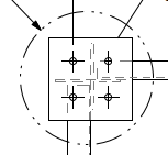
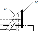
We are looking into doing an angle end plate splice. It feels unconventional to me, but I can't think of a logical reason why it wouldn't work so I am moving forward with it. The problem is that I can not think of a way to design all of it. Gusset/stiffener plate will be added to the angle to effectively make the profile at the end plate into a + shape with four bolts added, one at each corner of the end plate. I am feeling fairly confident in using the prying action approach in AISC steel manual to size the thickness of the end plate. My question is if there is any way to design the gusset/stiffener plates other than some rules of thumb. Like the thickness of the gusset ought to match the angle leg thickness so I don't get some eccentricities due to a difference in stiffness, and the length of the gussets down the angle I was going to set to a taper of 2:1 because, I don't know, it feels right...? I guess I don't have any sort of justification for that and I guess that is what I am looking for some help on.
 
Replies continue below

Recommended for you

That would have been a good idea. See attached.
 

Attachments

  • End Plate View.PNG
    End Plate View.PNG
    4.4 KB · Views: 43
  • Side view.PNG
    Side view.PNG
    4.3 KB · Views: 44
I was hoping to provide a meaningful comment but I can't make any sense out of your sketches.

In the big picture, what are you connecting to what? An angle to something else?
 
Sorry , I should have provided a better image. here is an Iso I have hopefully that illustrates it better. its a splice, so connection is more or less mirror with another angle end plate connectionISO.PNG The yellow highlighted angle is what connects into the yellow highlighted end plate. The gusset plates there are my main question. I'm trying to determine how long they should be.
 
yeah the white members are welded to the yellow angle, but there is a gap between the end plate and those members.
 
Below is a snippet from AISC DG-4 (on Bolted End Plate Connections) where they give some guidance on how to determine the stiffener thickness for an end plate stiffener. In this case:
tbw = beams web thickness
Fyb = Yield stress of the beam
Fys = Yield stress of the stiffener

1741123071173.png

There is also a section on preventing stiffener buckling.

1741123343826.png
 
seems like a messy load path, loads in white angles go
thru the gusset plates to the splice plate (which has 4 holes), and
thru the yellow angle to the splice plate

are the white triangle gusset plates also welded to the yellow angle?

can you add a "length" dimension to the gusset plates in the figure to show which dimension you are trying to calculate?

is this all field welded or assembled in a shop?
The load path isn't as bad is it might seam, there are some unavoidable eccentricities that I am dealing with. I'll make it work. The member going to the top right is mostly for stability and doesn't carry a lot a load. Overall this is a fairly lightly loaded structure.

Here is an update showing the dimension I am looking for. ISO.PNG
Those gussets are welded to the end plate and the yellow angle. The white member do not weld to the end plate. There is an unnoticeable space there.

This is a shop assembly.

Below is a snippet from AISC DG-4 (on Bolted End Plate Connections) where they give some guidance on how to determine the stiffener thickness for an end plate stiffener. In this case:
tbw = beams web thickness
Fyb = Yield stress of the beam
Fys = Yield stress of the stiffener

View attachment 6033

There is also a section on preventing stiffener buckling.

View attachment 6034
I didn't think of checking through DG4/16/30? because I was kinda hoping that maybe I could treat this connection as a pinned connection... yeah maybe not huh? I don't know. This is part of a truss assembly so I was hoping I could treat these connections as axial only-ish. The eccentricities are kinda screwing up any hope for that. But for this exercise, lets pretend that it is. Either way Its a good idea and I'll look through it and see if I can gleam and ideas. Thanks
 
This is part of a truss assembly so I was hoping I could treat these connections as axial only-ish. The eccentricities are kinda screwing up any hope for that. But for this exercise, lets pretend that it is.

I agree, there will be considerable eccentricity between the axial load in your angle and the connection.

For all the faffing about with these little stiffeners, I'd be inclined to just scrap them and make the end plate a bit thicker.

I think that you can use @JoshPlumSE's suggestion of the AISC DG stuff though. Yes, those are intended for moment connections. But every moment connection is a combination of an axial tension connection at one flange and an axial compression connection at the other. You should be able to massage the provisions for the axial tension flange connection to suite your purposes. Or, at the least, you can if you ignore those pesky eccentricities.
 
Firstly, I’d try to locate the bolts in the splice connection as close as possible to the centroid of the angle/weld group to avoid additional moment on the bolt group. This is likely something mirrored from what you show.

Then I’m with KootK, scrap the stiffeners and just go with a thicker end plate, unless that results in something obscene. Then you can go full science project and design for the portion of load required at the stiffeners to achieve the additional yield lines in your end plate via yield line analysis.
 
Delete the stiffeners (labor intensive and expensive), and make the end plate thicker.

What are the forces at the connection to the concrete? Can the anchor bolts be installed far enough apart to develop the required breakout strength.

There does not appear to be any consideration of tolerances. Are you planning to detail welded shim plates between the concrete and end plate?
 
Can you remove the gusset plates and use a thicker end plate? It might clean the connection up a bit.
 
Alright everyone thanks for the input. I appreciate it. I got focused on a solving the problem one way and made it more complicated than it needed to be. I just needed someone to help shake me out of my train of thought.
 

Part and Inventory Search

Sponsor