Continue to Site

Eng-Tips is the largest engineering community on the Internet

Intelligent Work Forums for Engineering Professionals

  • Congratulations KootK on being selected by the Eng-Tips community for having the most helpful posts in the forums last week. Way to Go!

Looped distrbution 4

Status
Not open for further replies.

Mbrooke

Electrical
Nov 12, 2012
2,546
Want some guidance and opinions on any one of these... real world experience also welcome.


1. What are the advantages of looping distribution feeders from other substations instead of neighboring feeders originating from the same substation? Assume ties are run normally open.


2. Advantages/disadvantages of looping with feeders from other substations and operating all reclosers (tie reclosers) in a normally closed state.

Here is an example single line of what I have in mind:


Open to any and all discussion.
 
Replies continue below

Recommended for you

1. Allows easy restoration of service in the event of a substation outage.
2. Circulating currents and sympathetic flows on the distribution system related to transmission flows. That is, you may have one substation trying to serve more load than normal (perhaps even backfeeding the substation transformer) depending on system conditions.
 
Overvoltage said:
1. Allows easy restoration of service in the event of a substation outage.

Thanks for the reply. Yes, this is a major pro- especially when you consider that many substations are never fully loaded.

2. Circulating currents and sympathetic flows on the distribution system related to transmission flows. That is, you may have one substation trying to serve more load than normal (perhaps even backfeeding the substation transformer) depending on system conditions.

Good point, I had not fully considered this.
 
Option 1: It is nice to have the ability for backup from both locations. A backup from another feeder at the same substation provides great flexibility for relay/feeder PCB testing without having to study load transfers to the adjacent substation. Having manually operated switches within a few blocks of each other saves driving time for the crew doing the switching. A backup from a remote substation makes it possible to keep customers in service during a planned substation outage. Most of our feeders have both local and remote options available.
Option 2 disadvantages:
*Feeders relay protection would be vastly more complicated. Instead of overcurrent relaying each devices would likely need directional/distance relays and telecommunications.
*Fault levels would go up.
*If advanced relaying isn't added, clearing times would go up dramatically.
*More customers exposed to a voltage sag during a fault.
*Voltage control via LTCs becomes quite different. Essentially all distribution bank LTCs would be in parallel with each other. A tap change in one substation affects reactive power flow in all adjacent substations. If not designed properly, this can lead to LTCs running in opposite directions from each other.
*Circulating current from transmission flows can easily be hundreds of amps on a 12.5 kV distribution system.
Option 2 advantages:
*Fewer customers exposed to a complete outage for certain fault locations.
 
@Bacon4Life: Well put. Regarding #1, I did some analyzing and it looks like feeder load-ability (in terms of voltage drop limits) goes down when looping with feeders from other substations with the intent of picking up most of the load instead of just the far end.

What do you load your lines to under none contingency conditions vs contingency in terms thermal or voltage limits?


Regarding #2: I'm glad you brought up tap changers, I would have missed that one. As you said relaying does get vastly more complex... I am evaluating the concept of putting directional, distance and fiber optic differential elements in reclosers. Nothing is set in stone and far from final, however the goal is two fold:

A. if a fault occurs on a line be it temporary or permanent, there wouldn't be any customer "blinks", only a voltage dip lasting a few cycles.

B. With the advent of parelleld cogenenration and renwables, it is becoming more obvious that distrbution systems need transmission level logic. If reclosers are getting this logic, why not put it to further use?


For maximum reliability with minimal circulating currents the two feeders in question should be supplied from opposite busses with a normally closed bus tie breaker between the busses.

CR

"As iron sharpens iron, so one person sharpens another." [Proverbs 27:17, NIV]
 
From an operations perspective, the ideal would be 50% loading so that each feeder could be directly transferred to an adjacent substation. In reality, some feeders are loaded much heavier and have to be split into sections. Most often voltage drop rather than thermal limits control how much load can be transferred between stations. Twice the load and twice the distance means four times the voltage drop.
We have a couple of stations that are paralleled through 208V secondary networks. It is kind of interesting that SCADA voltage records are too noisy to see LTC changes, but tap changes are perfectly obvious from the feeder MVAR readings jumping by about 0.5 MVAR per tap.
 
@Bacon4Life- Huge thanks- exactly what I've been theorizing.

In terms of 50% loading thats what I normally strive for, or at least the most lightly loaded segment being the one isolated. Reason being is that you need only two switching steps: one to isolate the faulted segment and another to close a normally open point to tie into an adjacent feeder thereafter. At high levels switching gets crazy... sometimes you even need to transfer load off the feeders you are transferring into lol. 50-60% is ideal.


The substation to substation system I am evaluating has the achilles heal of distance or load limitation- meaning a feeder with a normal loading of 200amps at 22kv can only be about 5 miles long from the source to the tie, because at the tie point you will be picking up to 160amps of load. Where as in a "mesh" system the feeders can run about 12 miles because even under worse case the extra load will only be traveling a shorter distance. Here is what I refer to when I say mesh BTW:


For those who have briefly paralleled separate feeders for one reason or another, what were the typical tie currents seen?

Similar but on a separate note- when calculating voltage drop as a lumped end load, does multiplying the final number by 0.5 yield a good approximation if the load was evenly distributed across the feeder?
 
For those who have briefly paralleled separate feeders for one reason or another, what were the typical tie currents seen?

As a power system operator, I've been doing this for years...and the answer is, as so often in engineering, "It depends."

I've seen transfer currents of almost zero amperes when going into parallel, typically when the two feeders share sources of virtually equal impedance; indeed it has happened that only when adjusting the ULTCs at either end of the parallel to move the null point to the device at which parallel is to be broken that actual changes in the supplying feeders' currents have been observed [ the general idea during load transfers is to have minimal reactive flow through parallel breaking devices ].

I have also seen [ unintended! ] flows of several hundred amperes, and at 44 kV, no less, when parallel has been made...

A good place to start is the almost-so-obvious-I-shouldn't need-to-say-it rule for load transfers that the load sharing between two paralleled feeders typically varies inversely as the impedance of the two supplies. I'll often see this when paralleling between one Dual Element Spot Network [DESN] station fed via two 125 MVA transformers and another with 83 MVA banks. There are occasions when, upon going into parallel, one of the two stations will "hog" the load, perversely often enough when the desire is to transfer the load in the other direction. In such cases we commonly unload one of the "hogging" transformer secondary windings by opening its circuit breaker so as to reduce the transfer through the parallel-breaking device to within its safe break capability. Sometimes we also do it just to reduce the voltage excursions experienced by our customers during switching operations.

when paralleling low-tension feeders between stations supplied at different system voltages [ in our case, generally between 115 kV and 230 kV supplied stations ], we almost invariably unload one secondary winding at the 230 kV station before even going into parallel.

Added via edit: When planning load transfers we also strive to ensure the high voltage grid level loop between the two stations to be paralleled won't be unduly long, as otherwise ugly phase angles can develop that will make stuff go boom and let the smoke out. In Hamilton, Ontario, for example, we have two stations that are fed from a pair of 115 kV circuits that are normally fed radially from two separate 230 kV stations via 230/115 autotrafo's, so if an LT parallel between two of the stations on opposite sides of the normally open 115 kV point is being planned we make arrangements to alter the HV system configuration as needed [ we have various options at our disposal ] so as to have both of the paralleling substations on the same 115 kV supply.

A relatively recent development is that with the advent of more and more distributed generation on our feeders, we have one more tool, namely generation dispatch, available to assist with adjusting flows prior to the breaking of inter-feeder parallels.

Hope this helps.
 
No need to hope, its of value to me :)

Have you ever done paralleling of 12.5 and 23kv distribution feeders? I ran some simulations and am getting under 50amps and no power "reversals" (feeding through) and it seems to good to be true. But as we know it depends- and in my case on 115kv outages that tie substations together.


Interesting read fwiw:


Have you ever done paralleling of 12.5 and 23kv distribution feeders?

The utility I work for does not, generally speaking, own any equipment that operates @ 12.5 kV, but we do have a few stations that supply one utility's feeders @ 23 kV and perforce our station's LT busses must therefore regulate @ that voltage...and we as operators are commonly most concerned with the voltage levels on the LT busses of our substations, and do not generally examine in any great detail the voltage profiles of the feeders themselves [line voltage drop is in view here], although from time to time there will be exceptions [aren't there always?].

[ Having said that, presentations @ the executive level have begun trickling down to the rank and file that there is a future push coming to modernize [read: add remote-controlled sectionalizing devices and telemetry], intensively model, and analyze in much greater depth, the performance of our LT networks, the overarching intent being to improve our SAIDI and SAIFI statistics. ]

Those sites are however the exceptions to that "rule"; we more typically operate LT systems @ a nominal 14 kV, the normal range of which can vary from 13.0 to 14.5, depending on location; 28 kV, which generally runs between 28 and 29 kV; and 46 kV, and although the latter is colloquially referred to as "44," its typical range is 45 to 46 kV. Feeder profile profoundly affects the normal operation of these feeders, load drop compensation typically being harnessed on only the relatively longer 28 and 44 feeders.

The NERC docs were indeed interesting reading...

CR

"As iron sharpens iron, so one person sharpens another." [Proverbs 27:17, NIV]
 
Glad you liked them. :)


Automation is one things thats making me play around with this idea, in the least when a contingency forces load to be transferred to another circuit, I do not want a second outage trasfering load back, so a brief instant in time feeders will be parelled. Longer if done manually. Simple, yet requires analysis.

I wash there was a tool so line men could test the phase angles across normally open tie points so they could determine on there own the ability to do closed transition load transfer.


BTW, one a side note- you want to know the secret to great SAIFI and SAIDI? Spacer cable. It pays for itself, and less need to automate everything.


crshears said:
Those sites are however the exceptions to that "rule"; we more typically operate LT systems @ a nominal 14 kV, the normal range of which can vary from 13.0 to 14.5, depending on location; 28 kV, which generally runs between 28 and 29 kV; and 46 kV, and although the latter is colloquially referred to as "44," its typical range is 45 to 46 kV. Feeder profile profoundly affects the normal operation of these feeders, load drop compensation typically being harnessed on only the relatively longer 28 and 44 feeders.


Typically under peak load worse case I start at 105%-106% of the nominal voltage and then let it run down to 95% of the nominal. 90% of the nominal at the far end for contingencies like picking up other feeds. Under light load the bus starting voltage may be confidently set at 101% 102% since VD is less. I think here we are in agreement.

 
If the voltages are equal magnitudes at the tie point, any voltage the line worker measures across the open point will be due to the phase angle.
 
I could come up with a predefined voltage. Any tips on what or how to obtain a good starting voltage? 100-200amps flowing through a tie are fine, above that no thanks.
 
In this system the primaries of distribution transformers form a loop. The loop circuit start from the substation bus-bars, makes a loop through the areas to be served and returns to the substation. The circuit provides for quick restoration of service in the case of transformer or feeder fault.

This circuit is very reliable but has a relatively larger cost. Also each side of the ring should not be loaded more than 50% of its rating as to accept the load of the other side in the case of fault.
 
@leur2011: Thank you for your post, I don't want it to go unacknowledged.

I'm correct to assume to loop is normally limited to about 6 miles from the bus-bars to the tie point? Making 12 total?
 
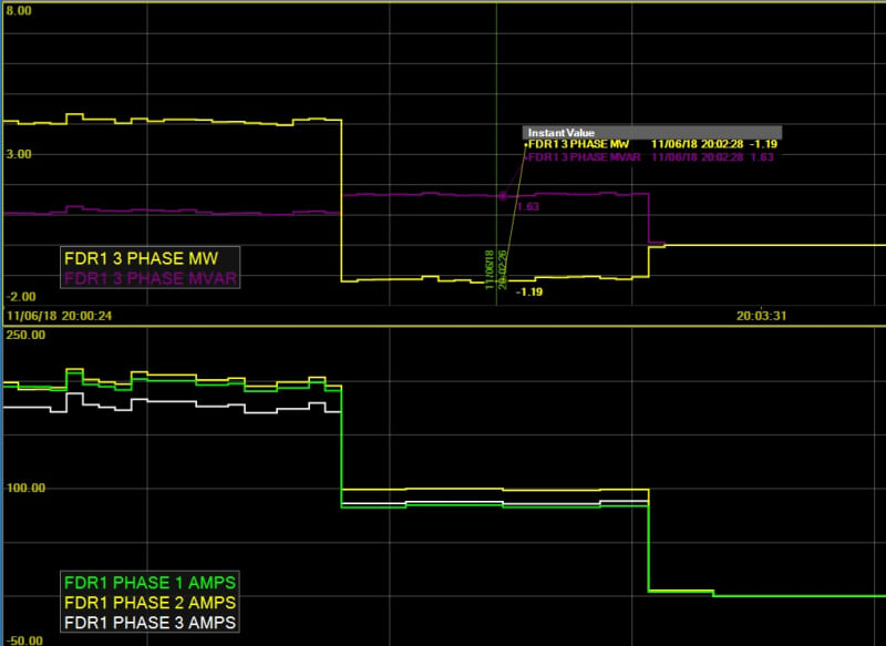
This trend shows the results of paralleling a small heavily loaded 12.5 kV transformer a one station with a larger lightly loaded transformer 1.5 miles away for approximately 80 seconds while moving load between substations. Real power flow switched from about 4 MW forward flow to 1 MW reverse flow. Voltage was matched between the substations, so there was very little reactive power flow.
feeder_tie_kx6wig.jpg
 
Nice trend there, Bacon!

Our network management system has the ability to create real-time graphs like that, and I frequently use a pair of them to track supply source real and reactive power flows while making parallel, adjusting reactive resources like tapchangers, establishing temporary parallel paths, unloading windings, and the like prior to breaking parallel, particularly where the breaking device is limited in its capabilities.

Unfortunately trying to post an exemplar here would be very difficult because of cyber security concerns...

CR

"As iron sharpens iron, so one person sharpens another." [Proverbs 27:17, NIV]
 
Status
Not open for further replies.

Part and Inventory Search

Sponsor