Eng-Tips is the largest engineering community on the Internet

Intelligent Work Forums for Engineering Professionals

LTB / critical lengths of Vierendeel walkway UNP side beams

Status
Not open for further replies.

Eagleee

Structural
Feb 14, 2017
51
0
0
DK
Gents,

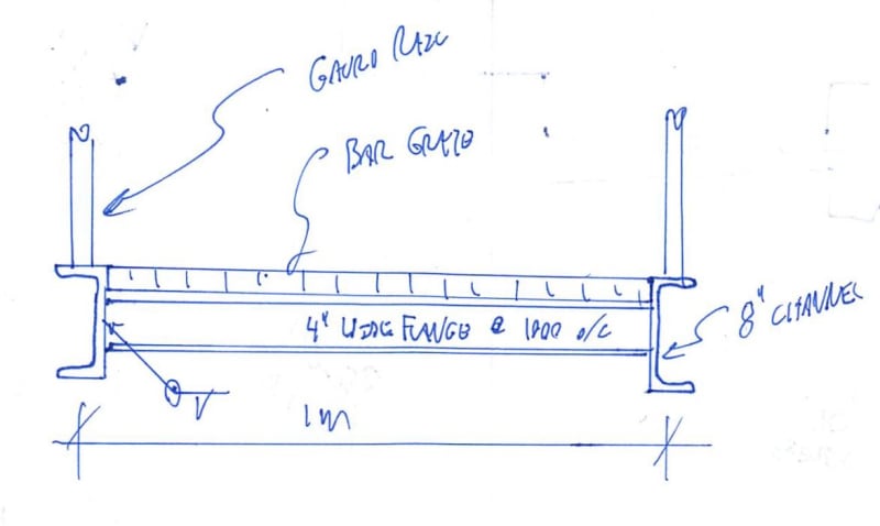
I am looking into design principles of aprox. 1m wide walkways as follows: side beams are UNP profiles (expected size about UNP200) and transverse beams per 1-1.2m, either fully welded IPE80-IPE100 in the 'center' of the UNPs; the load, length and support conditions for walkways following these principles vary (e.g. one walkway can be simply supported 10m span, another can be 6m double spanned). Lateral stiffness of the walkways is intended to be achieved considering Vierendeel action, rather than the more common solution of providing horizontal bracing. Because length, support conditions (and thus bending moment diagram shape) and loads vary, at this point I am looking into opinions and / or literature related to a general case, so to say. What I am specifically interested for this general care are the LTB parameters of the UNPs in the described layout.

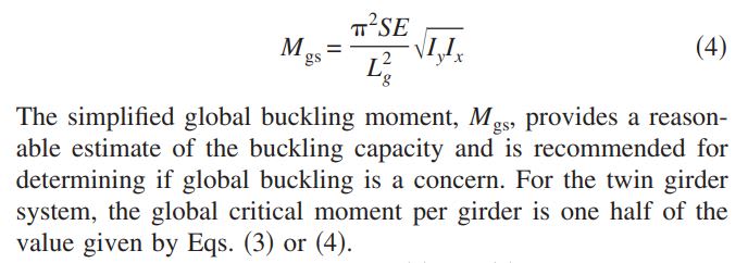
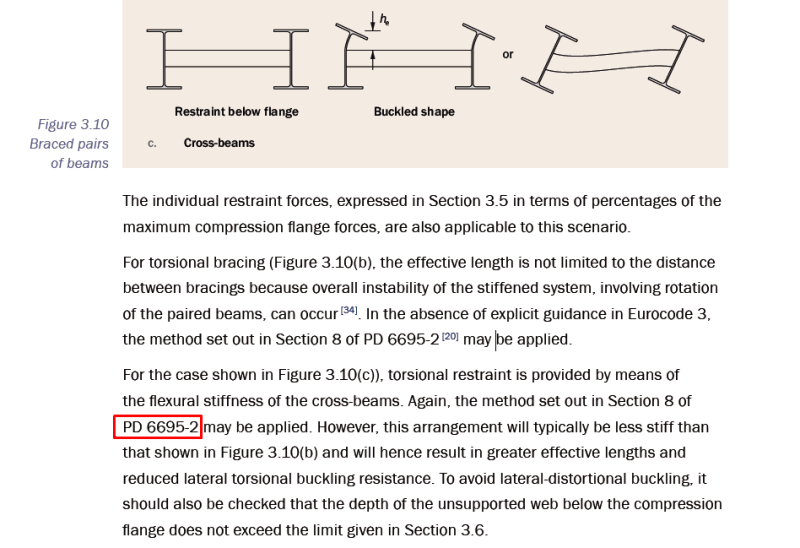
In SCI p.360 (Stability of steel beams and columns, freely available) I have found some reference to this type of situation (screenshot below); it seems further details that could be of use are given in this PD 6695-2 document which I do not currently have. Anyone around here familiar with this doc.?

Now, I should of course note I it could very well be that for many of these walkways, it will be other criteria that govern the UNP members e.g. deflections, eigenfrequency.

Any thoughts on the subject or directions to relevant literature are much appreciated.

Screenshot_1_ke7pah.png
 
Replies continue below

Recommended for you

Yura's article "Fundamentals of Beam Bracing" (also a free download) covers torsional bracing and gives straightforward design equations and a couple of worked examples.
 
Also try searching for U-frame bridges, eg BS5400 had design requirements and effective length calculation under this name IIRC. Half-though bridges and maybe pony trusses are other possible names for structures braced this way.
 
I think that you've got some options here.

1) Do the roll / diaphragm beam thing as described above by the gang.

2) Use your vierendeel truss as a bracing system in place of more conventional, trussed, plan bracing:

a) Apply the 25X guideline from your SCI document (may be difficult at 1m width), shown below AND/OR;

b) Figure out what strength and stiffness you'd need from a true plan truss and achieve those same parameters with your vierendeel truss.

Curious: what is the nature of the floor deck here?

c01_eiztl0.jpg
 
I think we should stop using the terminology vierendeel truss. Because unless I have misunderstood things then what we are discussing here is a fair bit different, though similarities can be drawn... From what I understand we are talking about torsional bracing to prevent LTB. Of course I could have things the wrong way around, Eagleee mentions 'lateral stiffness' and vierendeel action in the same breath as LTB. I argue that lateral stiffness and LTB are quite different beasts. Though they can be often solved by the same solutions. (AKA plan bracing). Most torsional bracing doesn't address lateral stiffness apart from providing a lateral load path to engage both beams.

I've designed numerous walkways as Eagleee has described. Lateral stiffness is rarely an issue.. But like many such questions we only have 20% of the picture.

Kootk said:
b) Figure out what strength and stiffness you'd need from a true plan truss and achieve those same parameters with your vierendeel truss.
I'm not sure this is the best approach, though it is likely to be conservative so fine in that respect. Generally torsional restraints to prevent LTB are orders of magnitude less stiff in plan than lateral restraints against LTB.
 
human909 said:
I think we should stop using the terminology vierendeel truss.

OP said:
Lateral stiffness of the walkways is intended to be achieved considering Vierendeel action, rather than the more common solution of providing horizontal bracing.

We'll leave it to OP to clarify but, unless my grasp of the language is slipping, it seems pretty clear to me that the floor deck will be in plane vierendeel truss.

human909 said:
I argue that lateral stiffness and LTB are quite different beasts.

Different beasts that can both be used to address the twin LTB buckling mode.

OP said:
From what I understand we are talking about torsional bracing to prevent LTB.

As far as I can tell OP has not put this limitation upon the conversation.

human909 said:
Generally torsional restraints to prevent LTB are orders of magnitude less stiff in plan than lateral restraints against LTB.

Right, but then they're not generally specifically designed to be vierendeel trusses. OP brought up the vierendeel trusses and their relation to LTB so that what I spoke to. And I acknowledged that it might be inefficient.

KootK said:
a) Apply the 25X guideline from your SCI document (may be difficult at 1m width), shown below AND/OR;

Developing composite action between the two beams really is quite an elegant solution. It effectively steers the situation back towards [Iy > Ix therefor AOK].
 
Kootk said:
We'll leave it to OP to clarify but, unless my grasp of the language is slipping, it seems pretty clear to me that the floor deck will be in plane vierendeel truss.

That is far from clear to me. A floor deck is even further away from a Vierendeel truss. The post never mentions or includes the floor deck so I would assume that they are not including it as part of their structural system. It would seem the OP is considering the traverse (IPE80-IPE100) to be two sides of the 'vierendeel' truss being mentioned.

Anyway, I would seem most if not all our disagreement hinges on interpretation of the original post. So not much to be gained discussing this unless this is elaborated on.
 
human909 said:
So not much to be gained discussing this unless this is elaborated on.

I agree completely. That's why I found it odd that you suggested that we stop discussing vierendeel trusses when, from my perspective, that's precisely what OP was asking about. If I'm out to lunch on that, I'm sure that we can rely on OP to let us know.

human909 said:
That is far from clear to me. A floor deck is even further away from a Vierendeel truss.

I didn't mean to suggest that that a solid floor deck physically IS the vierendeel truss. What I meant was:

There is a vierendeel truss within the assembly that forms the floor deck of this walkway thing. There is a floor deck AND a vierendeel truss.

My assumption is that there is some kind of walking surface here installed over top of of the vierendeel truss. But I don't know if that's concrete slab, wood decking, or bar grate. And I don't konw if it ties into the top of the beams or the bottom but, given the presence of the vierendeel truss webs, I suspect that it's closer to the top. obviously, these answer may have significant implications for the question at hand.
 
Is this right? For a 10m span? I had to google all of the size as they were literally and figuratively foreign to me.

As for twin mode LTB on the channels, there's zero chance of that at these proportions based on torsional bracing alone. Your system warping torsion resistance will be way to great for that. Any vierendeel benefit will just be an unecessary bonus. I think that you can call your unbraced length the distance between the cross frames and call it good.

c01_iye0i5.jpg
 
sorry for the late check-in. appreciate all the answers.

human909 said:
But start by having a ready of this which might clarify some things to you.
Thanks a lot. I've only just skimmed the first few posts and I can tell it will be of good use. I will come back after having a thorough look. If this is not a sign I missed reading up on this forum a bit too much I dont know what is :)

steveh49 said:
Yura's article "Fundamentals of Beam Bracing" (also a free download) covers torsional bracing and gives straightforward design equations and a couple of worked examples....Also try searching for U-frame bridges, eg BS5400 had design requirements and effective length calculation under this name IIRC. Half-though bridges and maybe pony trusses are other possible names for structures braced this way
I will look into both.

KootK said:
Curious: what is the nature of the floor deck here?
These are walkways inside the global structure and do not fulfill any global bracing roles. From their supports, all lateral load on them goes to the bracing system. Lateral load is generally small and mainly generated by mass loads; i can see now why my use of the vierendeel truss term may have led to some confusion as to the purpose of these structures.

KootK said:
2) Use your vierendeel truss as a bracing system in place of more conventional, trussed, plan bracing:

a) Apply the 25X guideline from your SCI document (may be difficult at 1m width), shown below AND/OR;

b) Figure out what strength and stiffness you'd need from a true plan truss and achieve those same parameters with your vierendeel truss.
interesting indeed. did a mental note on this one. i would have had the same approach as you suggest if that were the case.

human909 said:
I think we should stop using the terminology vierendeel truss. Because unless I have misunderstood things then what we are discussing here is a fair bit different, though similarities can be drawn... From what I understand we are talking about torsional bracing to prevent LTB. Of course I could have things the wrong way around, Eagleee mentions 'lateral stiffness' and vierendeel action in the same breath as LTB. I argue that lateral stiffness and LTB are quite different beasts. Though they can be often solved by the same solutions. (AKA plan bracing). Most torsional bracing doesn't address lateral stiffness apart from providing a lateral load path to engage both beams.
as I said above, perhaps I could have phrased the topic better. My thought was simply to mention how lateral stiffness is achieved in the first place.

human909 said:
I've designed numerous walkways as Eagleee has described. Lateral stiffness is rarely an issue.. But like many such questions we only have 20% of the picture
I hope I bumped that number up with this post. Lateral stiffness I agree should not be an issue. In your experience then, how does the critical length of the beams (i include here a critical length back calculated from a critical moment found via a buckling analysis) look like, at least for these proportions? Is the first buckling mode of the side beams of such a welded assembly in between the transverse beams?

KootK said:
We'll leave it to OP to clarify but, unless my grasp of the language is slipping, it seems pretty clear to me that the floor deck will be in plane vierendeel truss.
I have not mentioned that the actual flooring is grating as I did not want to involve its possible beneficial effects. But yes, it will be an in plane vierendeel truss.

KootK said:
As far as I can tell OP has not put this limitation upon the conversation.
Absolutely not. I am quite interested actually also in any branch away ideas which do not apply to my specific situation.

KootK said:
Is this right? For a 10m span? I had to google all of the size as they were literally and figuratively foreign to me.
nailed it. flooring is grating indeed. sections used in the post are indeed european...i have to converse units when reading this forum all the time, so ha! but yeah, so for these section sizes you would expect the critical length to be the length of the segment between transverse beams? what happens when the proportions start changing? i could see the side beams going to 300mm height (for other reasons such as serviceability), but not much more than that.
 
In the thread that retired13 sent you to, you will find the snippet below which provide a quick and dirty method of evaluating if global LTB is worthy of more detained consideration. I'd personally start with that and then only dig deeper if that check indicated a problem.

OP said:
...so for these section sizes you would exp
c01_qa9h9s.jpg
ect the critical length to be the length of the segment between transverse beams? what happens when the proportions start changing?
 
Eagleee said:
so for these section sizes you would expect the critical length to be the length of the segment between transverse beams
Approximately yes. But it depends on the stiffness of the transverse diaphragms. Do a buckling analysis to check.
 
Status
Not open for further replies.
Back
Top