Continue to Site

Eng-Tips is the largest engineering community on the Internet

Intelligent Work Forums for Engineering Professionals

  • Congratulations KootK on being selected by the Eng-Tips community for having the most helpful posts in the forums last week. Way to Go!

LVL Beam Reinforced by Steel Plate 3

Status
Not open for further replies.

JohnTerry4

Geotechnical
Apr 8, 2020
12
Hello,

I have a 5.25" x 11.875" LVL beam that is spanning 18 feet that was installed at a project but it is not sufficiently sized to carry the bending forces from the weight above. Therefore, I am considering adding a steel plate to the bottom of the beam as a reinforcement measure, and screwing the plate to the LVL beam every 12-inches or whatever so that the plate and the LVL can behave as one beam. Any guidance as to how I should calculate the new moment capacity?

TIA,
Feras
 
Replies continue below

Recommended for you

Agree with the above. Adding plate to the bottom and connecting it for shear flow is dubious at best. There's too much fastener slip in wood to adequately engage the steel in that configuration before excessive deflection has occured.
 
Thank you, but I am unable to do that for logistical purposes, which is why I wanted to install on bottom.
 
There’s a very simple calc for that which I will outline below:

Additional moment capacity provided by plate fixed to bottom = 0kNm.

 
You can try, but I think you will find it very difficult to develop the connection of the plate to the wood. The capacity of the screw in the wood will be too low.
 
Okay, so I might be able to attach a steel plate vertically to only ONE side of the existing LVL beam. Is this better?
 
One thing to be careful of in these types of scenarios is the fact that your LVL beam is already carrying the entire load. So you'll need to factor that into your calculations. Effectively if the load was never to vary say, then simply putting a steel plate onto the side would mean the steel plate wasn't taking any load at all, you have not taken load off of the LVL member which you've acknowledged may be overloaded. The loads obviously increase periodically after adding the reinforcement, but you need to be careful that you avoid the timber failing given the proportions of the load locked into it before the reinforcement.

For the steel plate to take some proportion of the original load you'd have to jack load out of the original beam and get it into a neutral position before adding any reinforcement and then releasing the load so it's shared like it would have been if built like that from the start.

I'm not aware of any guidance for adding a single plate one side. It's usually a plate central, or a symmetrically placed plate either side for flitch beams.

Worst case it sounds like you'd be able to prop and take beam out and replace with steel given you can probably fit something appropriate within the original beam size and pack it out and reconnect to joists or whatever is supported.

There have been quite a few threads over the years on flitch beam design, so those discussions might give you some ideas if you have a search.


I agree a side plate is better since you don't need to provide connections for shear flow. Predrilled holes will allow slip. Also it may take a LOT of fasteners, and there is still some slip with screws directly into wood.

My gut says a plate on one side would be acceptable for such a stocky section, but I'm not sure about it. Also agree with above that if the beam is already loaded you would want to jack it up.

 
For an 18 ft span, 11 7/8" LVL, I think you would be hard pressed for it to be overstressed in bending before it had serviceability issues - unless you are designing to minimum code.
 

not with LVLs and that ilk... but, I've done that with dimensioned lumber lots of times and used adhesive in addition to screw fasteners... how much added strength is required?


Rather than think climate change and the corona virus as science, think of it as the wrath of God. Feel any better?

-Dik
 
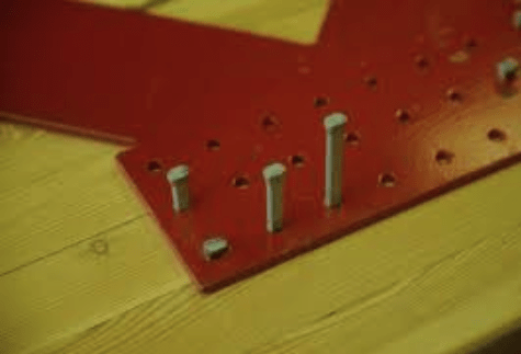
I had a similar problem with a glulam beam some years ago. I used a steel plate, same width as the beam and fastened it to the underside of beam using glulam rivets. The plate was pre-drilled in the shop to accommodate the rivets.

To avoid the issue raised by Agent666, the plate was jacked at midspan, relieving the wood beam of some dead load stress. Glulam rivets were installed from midspan toward each end of the beam. Took a lot of pounding, but it seems to have worked okay. I expect it would work just as well with an LVL beam.

BA
 
Feras Ayoub said:
...only ONE side of the existing LVL beam.

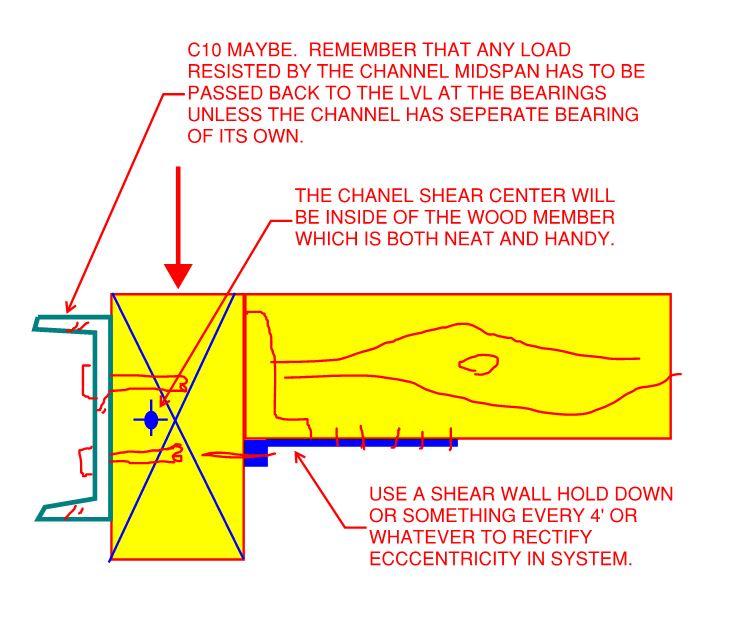
The asymmetry of the setup does result in some additional nuances which, I suspect, is what you were alluding to with that comment. The addition of the plate to the opposite side that the load is coming into basically shifts the shear center of the combined assembly further from the loaded face. Some additional ideas below...

C01_uegx5d.jpg
 
BART... sorry I've used it with glulam as you note... forgot and used preflex as you note. Glulam rivets are the greatest thing since sliced bread...

Rather than think climate change and the corona virus as science, think of it as the wrath of God. Feel any better?

-Dik
 
That's right dik, and there is very little slip with glulam rivets because they fit so tight in the drilled holes.

image_k6whn8.png


BA
 
They deform the 3/16" min side plates and wedge into the hole...

Rather than think climate change and the corona virus as science, think of it as the wrath of God. Feel any better?

-Dik
 
Status
Not open for further replies.

Part and Inventory Search

Sponsor