Continue to Site

Eng-Tips is the largest engineering community on the Internet

Intelligent Work Forums for Engineering Professionals

  • Congratulations SDETERS on being selected by the Eng-Tips community for having the most helpful posts in the forums last week. Way to Go!

Machine building exercise 1

Gyco

Student
Mar 27, 2025
20
The figure (attached) shows the arm of a lift in the particular position in which while the adjustment tie rod CB is horizontal, it also happens that the section of the lifting cable DE is horizontal. With the measurement dimensions and with the mass M = 500 kg to be lifted, the loads on the hinges A, B, C and on the pin D of the pulley are calculated; also choose the profile and dimensions of the arm AD.

exercise 2 construction solution: Make a construction drawing of the connection between the arm and the pulley (D) and between the arm and the hydraulic piston (B)
My hypothetical solution is the following:
equilibrium condition of the point of material of mass M, or T = Mg directed upwards, applied to the center of gravity. Then considering the pulley for the 3rd principle of dynamics there is tension of the wire acting in the downward direction equal to T.
To derive the reactions of the hinges I thought of calculating the moment with respect to the intersection of the points A and C (bottom point) in order to eliminate 3 reactions out of 4 in the hinges A and C. What does not make sense to me is that I cannot calculate the distance between C and D for reactions in D. I hope that someone can give me a hand in the resolution.
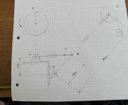
IMG_7669 15.26.54.jpg
 
Replies continue below

Recommended for you

sorry, but what ? are you interpreting B as a fixed point ? I think everyone else thinks CB is pinned onto AD; how could it be otherwise (unless by design error) ?

I guess, as a school exercise, if it isn't stated then you make that assumption as part of your solution.
Well it depends I was deciphering this a crane.
But that was a mistake. It should be lever.
B has MG, right? That is were center of gravity is of the lever, correct now force vector the is the weight in N. Ugg, I think the problem with the geometry is not well defined, and assuming
Right or wrong. Late in the evening my brain is turning to mush.
The figure (attached) shows the arm of a lift in the particular position in which while the adjustment tie rod CB is horizontal, it also happens that the section of the lifting cable DE is horizontal. With the measurement dimensions and with the mass M = 500 kg to be lifted, the loads on the hinges A, B, C and on the pin D of the pulley are calculated; also choose the profile and dimensions of the arm AD.

exercise 2 construction solution: Make a construction drawing of the connection between the arm and the pulley (D) and between the arm and the hydraulic piston (B)
My hypothetical solution is the following:
equilibrium condition of the point of material of mass M, or T = Mg directed upwards, applied to the center of gravity. Then considering the pulley for the 3rd principle of dynamics there is tension of the wire acting in the downward direction equal to T.
To derive the reactions of the hinges I thought of calculating the moment with respect to the intersection of the points A and C (bottom point) in order to eliminate 3 reactions out of 4 in the hinges A and C. What does not make sense to me is that I cannot calculate the distance between C and D for reactions in D. I hope that someone can give me a hand in the resolution.
View attachment 7277
This drawing makes no sense
 
sorry, but what ? are you interpreting B as a fixed point ? I think everyone else thinks CB is pinned onto AD; how could it be otherwise (unless by design error) ?

I guess, as a school exercise, if it isn't stated then you make that assumption as part of your solution.
the text says that B is a tie rod and you have to calculate the loads on C and B, interpreting that on CB there is a horizontal force HB. This is what I reasoned.
 
The force on B and C is "F," which I showed how to determine. Most tie rods have pinned connections because they don't need to be strong enough to withstand bending loads and so they aren't made to withstand bending loads.
 
The force on B and C is "F," which I showed how to determine. Most tie rods have pinned connections because they don't need to be strong enough to withstand bending loads and so they aren't made to withstand bending loads.
The loads on hinges C and B to be determined are written in the text.
 
and those loads are "F" ... ? CB is a "two force member". Don't get the question, what else do you think is happening ? If I haven't understood you (that the joint between CB and AD is a pin) please explain.
 
and those loads are "F" ... ? CB is a "two force member". Don't get the question, what else do you think is happening ? If I haven't understood you (that the joint between CB and AD is a pin) please explain.
in the sense that the section CB is a regulation tie rod therefore subject to two equal and opposite forces applied to the ends plus we have the force F applied in B (which is a hinge as the text says) which is unknown to determine. Since B is a hinge it will have two components
 
I don't know what you mean. I see this as a crane arm (AD) with a control arm (BC) and the two are pinned together at B. There cannot be a joint in AD at B, making it two members (DB and BA). Fiddle with the pen on your desk, to see how this works. I think the text is saying that BC is pinned, "hinged", on AD at B. If unclear, ask a TA.
 
see if this helpfull. when two ropes are connected to a beam
To calculate tension in a system with two pivot points, you need to consider the equilibrium of forces and moments. You'll typically use the principle that the sum of forces and the sum of moments (torques) around any point must equal zero for the system to be in equilibrium.

Here's a breakdown of the process:


1. Identify the Forces and Pivot Points:
  • Forces:
    Identify all forces acting on the system, including tensions, weights, and any other applied forces.

  • Pivot Points:
    Determine the locations of the two pivot points and the distances between them and the points where forces act.

2. Choose a Pivot Point for Moment Calculations:
  • One Pivot Point: Choose one of the pivot points as the point around which you will calculate moments.
  • Other Pivot Point: The other pivot point will be used to calculate the other unknown force.

3. Apply the Equilibrium Conditions:
  • Sum of Forces:
    Ensure that the sum of all forces in both the x and y directions is equal to zero.

  • Sum of Moments:
    Calculate the moments (torques) around the chosen pivot point. The sum of all moments must also equal zero.

4. Solve for Unknowns:
  • Set up Equations:
    Create equations based on the equilibrium conditions, using the known forces, distances, and the unknown tensions.
  • Solve the System of Equations:
    You'll typically have two equations (one for forces and one for moments) with two unknowns (the tensions at the two pivot points). Solve this system of equations to find the tensions.

Example:

Imagine a beam supported by two ropes at points A and B. Let's say:

  • The beam has a weight W acting at its center.
  • The distance between point A and the center is 'a'.
  • The distance between point B and the center is 'b'.
  • The tension in rope A is T1.
  • The tension in rope B is T2.

Steps:
  1. Identify Forces: T1 (upward), T2 (upward), W (downward).

  2. Choose Pivot Point: Choose point A as the pivot point.

  3. Equilibrium Conditions:
    • Sum of Forces: T1 + T2 - W = 0.

    • Sum of Moments (around A): T2 * (a + b) - W * a = 0.
  4. Solve:
    • Solve the second equation for T2: T2 = (W * a) / (a + b).

    • Substitute this value of T2 into the first equation and solve for T1: T1 = W - T2 = W - (W * a) / (a + b) = (W * b) / (a + b).

Key Points:
  • Direction of Forces:
    Pay close attention to the direction of forces (upward, downward, left, right) when setting up your equations.

  • Moments:
    Remember that moments are calculated as the product of force and the perpendicular distance from the pivot point to the line of action of the force.

  • Equilibrium:
    The system is in equilibrium when the sum of forces and the sum of moments are both zero.
 

Part and Inventory Search

Sponsor