Eng-Tips is the largest engineering community on the Internet

Intelligent Work Forums for Engineering Professionals

Machined Flanged Pipe Spool

Status
Not open for further replies.

MattNCSU03

Mechanical
Sep 22, 2005
48
0
0
US
I'm designing a fluids test loop in a laboratory and need to design and have fabricated a short pipe spool with flanged ends. I initially modeled something with a WN flanges and a short section of pipe but because I needed to fit in half a dozen instrument taps and a NPT branch connection within a short overall length, I thought it would be much easier to machine something from a bar. We're also concerned with weld distortion to the inner bore from welding all the bosses required.
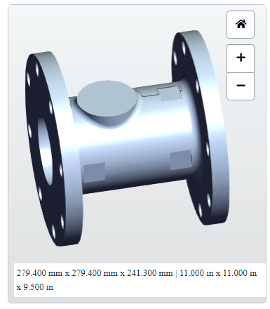
Spool Description:
Side 1: 4" Class 150 flat-faced flange
Side 2: 6" Class 150 flat-faced flange
bore: 4.03"
branch 1: 2" NPT
branch 2: 3/8" NPT (drain)
Misc: 6x 5/8" instrument ports around circumference (2 as close to side 1 as practicable and 4 as close to side 2)
Nominal thickness: 0.75" (set at so instruments can sit on a flat machined into the OD vs on a boss)
Overall length: 9.5"
Design conditions: water @ <100 psi / < 100°F
older preview image (hasn't been updated to reflect smaller side 1 flange):
spool_ajqavm.png


Our pressure safety board prefers test loops and components to be designed to an ASME code, BPVC and B31.1, 31.3, or 31.9 when possible. This loop is low enough pressure/temp I could use 31.9 per our rules.

With an eye to making the above spool code compliant, it looks like I could have it rough forged and then final machined to meet B16.5 (not sure about meeting 6.12.6 for auxiliary port size, depends on what "unless otherwise specified" means..e.g. by the code or user) or fully machined from a bar by using BPVC VIII.1 UG-14(b)(4). Am I missing something or making this overly complicated?

Thanks in advance for the advice!

Matt
 
Replies continue below

Recommended for you

Hi Matt. Where are you located? Is this for testing purposes (as you mentioned) or for actual process applications in a proces environment (since you mentioned pressure safety board)? For the latter, assuming B31.9 to be applicable, I’d suspect this to become something under 904.7.2, though I’m unfamiliar with B31.9.

Huub
- You never get what you expect, you only get what you inspect.
 
Located in the US. Pipe and flanges are readily available here. Using standard weld neck flagnes, I'd have to weld bosses on to the tapered part of the weld neck in order to get the proper instrument spacing within the same overall length. Not sure if that is allowed.
 
I understand your consideration. Either way, x04.7.2 will probably be applicable. I understand why you'd weld machine this from bar or forging though.

Huub
- You never get what you expect, you only get what you inspect.
 
I don't see why you couldn't weld something to the neck of a flange as long the odd angle is accommodated.

Einstein gave the same test to students every year. When asked why he would do something like that, "Because the answers had changed."
 
Matt,
I wouldn't bother too much on it. In terms of ASME B31.3, its a Category D fluid service. as long as you make the instrument toppings by listed couplings/half-couplings and smaller than NPS 2, you should be good to weld the branch connections. For branch connection spacing, follow PFI Standard ES-7 acceptable to ASME B31.3, without having to deal with reinforcement.

GDD
Canada
 
A few things.

1) I would consider using a long weld neck flange, although hub lengt is only 229mm for a 4"
2) How are you going to weld a 6" flange onto a 4" piece of pipe?
3) A bore of 4.02" with a wt of 0.75" isn't a 4" pipe....
5) These flat spots machined in create some stress concentrations which are unusual, though at low pressure probably ok.
6) Does the branch need to be in at one end?

I think you're much better off trying to use standard components which you fit together so use long weldneck flanges, tees, weldolets or could you make this out of something like PE?

Remember - More details = better answers
Also: If you get a response it's polite to respond to it.
 
If the overall length of 11.5" is fixed it will be difficult to use off-the-shelf fittings unless maybe slip-on flanges welded to a reducer.
 
Bore holes in 2 blind Flanges. Weld pipe between the blind faces. Much easier than boring a bar.

Einstein gave the same test to students every year. When asked why he would do something like that, "Because the answers had changed."
 
Thanks for the replies, for some reason I'm not getting email notifications despite it being turned on.

To address a few of the questions, the 4.02 bore came 4" SCH40 weld neck flanges that I was originally using. I recently discovered long weld neck flanges and maybe I could take a 4" LWNF and weld it to a 6x4 reducing LWNF but I would have to shorten them both to keep the 9.5" overall length. I'd still be concerned about weld distortion in the bore caused by welding all the required couplings so I'd probably have to specify SCH60 or 80 and then bore it out to SCH40. If I'm modifying catalog ASME pressure equipment, what process do I need to go through to say its OK to use?

I came from a large AE doing power plant design/construction so I appreciate all the various options for assembling a spool but now I'm in a fluids laboratory where data integrity is king. The location of the branch and instrument ports are all tuned to study specific flow phenomena. The flat spots in the image are all bored out, not sure why the preview showed them capped. I'd designed the flats with manufacturability in mind to minimize material removal and 4-axis continuous machining. I hadn't thought of stress concentrations and will add radii to mitigate.


----
Edit: auto-correct substituted maneuverability for manufacturability
 
The boring out once you finished welding etc to me isn't a "modification", it's just a manufacturing element. As long as your design works with Schedule 40 thicknesses then you're good to go.

LWNF lengths are a maximum and you can shorten them as required.

Those flat spots would need to be thought of as the minimum thickness so you might need thicker pipe than you think to avoid having to do an FEA on it.

Remember - More details = better answers
Also: If you get a response it's polite to respond to it.
 
Why not just machine it out of bar?

As long as it is an appropriate material, it will be plenty strong enough, and you save all the complications and data integrity risks from welding.
 
Why not 3D print it?
100 psig shouldn't be too difficult.
Seems like that would be possible to do on my Genius printer.


Einstein gave the same test to students every year. When asked why he would do something like that, "Because the answers had changed."
 
Status
Not open for further replies.
Back
Top