ismailtag
Mechanical
- Dec 9, 2015
- 5
Hi everyone.
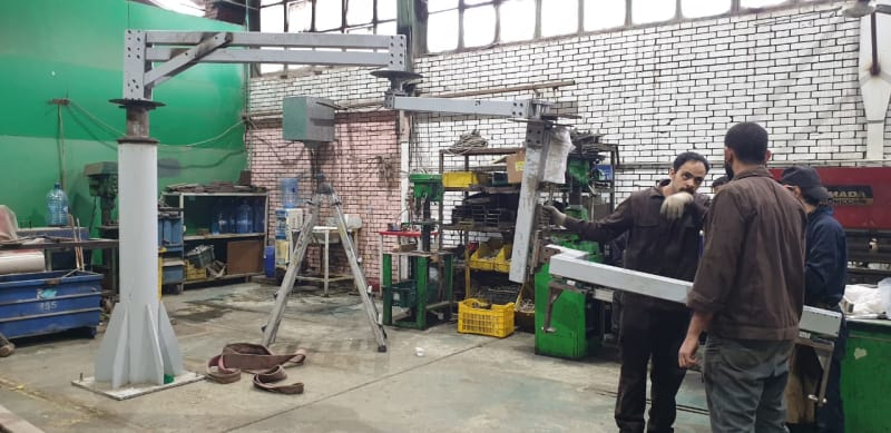
I am designing a manipulator to hold the dashboard in an automotive company, the manipulator is supposed to carry a load of about 120 Kg at a maximum distance of 5 meters and it is used to transport that payload inside the car.
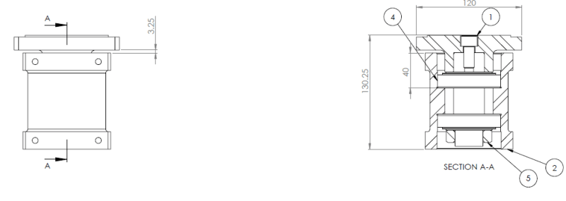
So I designed a system to have several rotational links and one linear motion at the end of the manipulator. As you imagine there is alot of axial load and moment, so I designed the bearing blocks for the rotational links as two taber bearing in an X configurations as seen in this image.

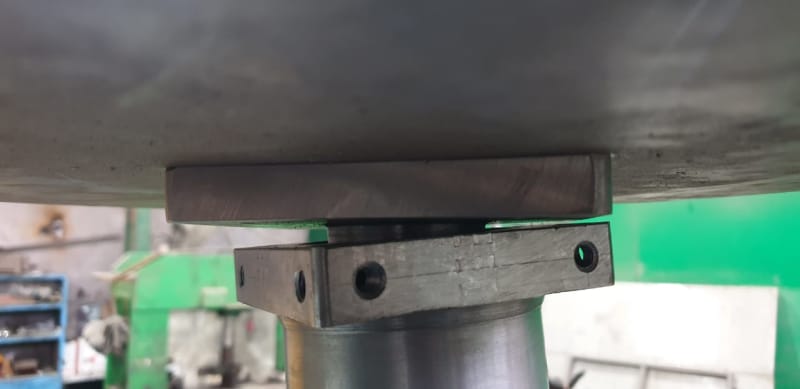
my current problem is that when I add the final link of the system, the manipulator deflects greatly at the bearing blocks as seen in the image.

Deflection at the bearing block

I have tried changing the bearings to larger sizes but its the same problem, I think its a problem of selection of taber bearing. is there any other bearing selection(I have thought about using a compination of thrust bearing and roller bearing) that would solve this problem or is it a problem of needing counterweight or wires to support the system?
I really need your support in this, appreciate any responses, thanks
I am designing a manipulator to hold the dashboard in an automotive company, the manipulator is supposed to carry a load of about 120 Kg at a maximum distance of 5 meters and it is used to transport that payload inside the car.
So I designed a system to have several rotational links and one linear motion at the end of the manipulator. As you imagine there is alot of axial load and moment, so I designed the bearing blocks for the rotational links as two taber bearing in an X configurations as seen in this image.

my current problem is that when I add the final link of the system, the manipulator deflects greatly at the bearing blocks as seen in the image.

Deflection at the bearing block

I have tried changing the bearings to larger sizes but its the same problem, I think its a problem of selection of taber bearing. is there any other bearing selection(I have thought about using a compination of thrust bearing and roller bearing) that would solve this problem or is it a problem of needing counterweight or wires to support the system?
I really need your support in this, appreciate any responses, thanks
