Eng-Tips is the largest engineering community on the Internet

Intelligent Work Forums for Engineering Professionals

Massive Residential Roof Cantilever - And Discontinuous Top Plate

Status
Not open for further replies.

Ashke15

Structural
Mar 9, 2023
16
0
1
US
Hi all,

Working on a residential structure that suddenly got way more complicated after a bunch of changes from the owner. A quick rundown of the project:

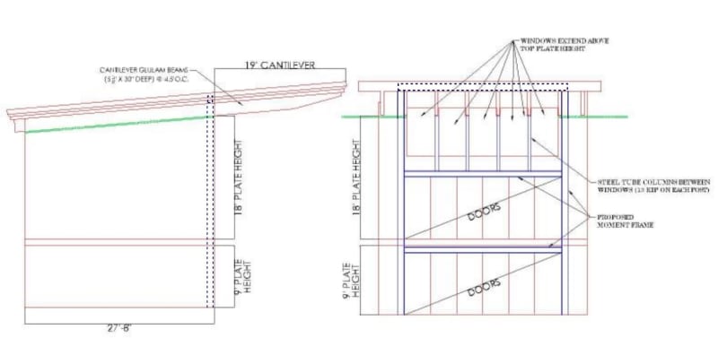
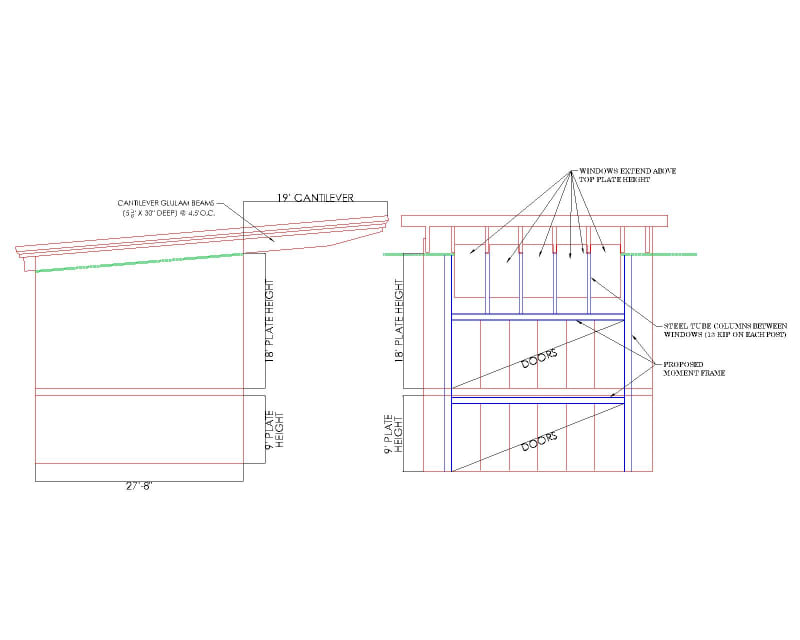
- Rectangular wood-framed structure
- Tall main floor (18' plate height at the tall end)
- Concrete foundation walls for 9' basement with framed walkout at the rear
- Glulam beams form the roof and cantilever out 19'. Rafters run over the top of the glulams
- Top plate at the front and rear is broken by windows that stick up above the top plate

Problem #1: I had originally planned on a steel moment frame at the back of the structure. Previously the windows did not stick up through the top plate so this would have been easy. Now I can't get a steel beam over the top of the windows for the frame. See the sketch below for a new proposed steel frame. Wondering if it's ok to say that the lateral load from roof diaphragm goes into the glulam beams, then into the steel columns between the windows, then into a lower steel beam over the doors.

Problem #2: The glulam beams originally cantilevered out 5'. Now they go out 19'....I've got 5 1/8" x 30" glulam beams to work. However, I'm thinking they need to be laterally braced at the cantilever to prevent twisting, but not sure how to do that since I'm sure they won't want to see bracing between the glulams. Also, I've never done a cantilever even close to this long and am thinking I'm probably missing something.

Any thoughts on these issues I'm facing on this project? I appreciate any advice or feedback that you may have.

Elevation_Views_dlpniz.jpg
 
Replies continue below

Recommended for you

So there is no wall under the roof joists? Man these architects are taking the whole "add windows and delete wall space" thing to the extreme these days. It's not bad enough that there is no wall sheathing just glass, we are even losing the floor/ roof cavities too.

I don't like it. I don't like it in-plane and I don't like it out-of-plane either. I don't see how you wouldn't get excessive racking from wind loads.

There are times where we need to draw the line as engineers and this would be one for me.
 
In -theory- the problems are relatively simple, you just follow engineering principles and track the load the whole way to ground
If you want to send it through the beams and down into the frame then you could, provided you detail and design for that

However, in practice I think the solutions are going to end up looking pretty god awful.
30' is a ginormous cantilever and I would be nervous doing it out of timber, especially as (if I understand the sketch) I think the beams are exposed?
I would be very careful with the cantilevers to limit my design to absolute deflections not L/150 or whatever you would normally do
The cantilever edge will be highly visible so absolute deflections will be seen and govern occupant/pedestrian amenity concern
Wetting and drying effects will have significant implications on this - they will exacerbate long-term creep deflections so I expect that roof will sag a lot with time

I would be sticking a thick plywood roof diaphragm over the beams but would be nervous if I couldn't put any blocking in at all - it won't really work structurally without it, and blocking is highly critical with this size of cantilever to tie them all together
Otherwise you will end up with a) beams trying to roll b) varying roof pressures across the roof will make each cantilever go up and down individually

Whilst I said the load path could be theoretically designed and detailed, I think it's pretty dumb around those windows. I would be trying to change that window height to get a steel beam at the top
I think the architect and client need some input from their specialist structural consultant to suggest design revisions, beginning with those high level windows
 
This looks a little crazy to me, but it seems that window walls like this are becoming more common on these custom houses. I like how the architect changed the cantilever from 5 ft to 19 ft, not 5 ft to 6 or 7 ft, but 19 ft!

I would be real concerned with the glulam supports and what's keeping the glulams from rotating/racking there. I don't see the steel columns at the bottom providing much restraint in that respect.

With the steel moment frame, could you run a steel beam above the glulams at the level of the roof rafters? That would provide a direct load path for the roof diaphragm forces into the moment frame. It might even be possible to support the glulams from above with the steel beam, although I'm guessing you don't have enough depth there for a steel beam deep/strong enough to pull that off. Personally, I don't like supporting things this way and I'd have to contemplate this more before I would do it, but it could be an option for you.
 
Maybe with a full-height saddle you could get the lateral out of the diaphragm and into the frame next story down. That would be asking a lot of the Glulams to discretely take that load out.
I don't know, honestly, if it was me, I would walk away.
 
Woof

Can you utilize the space above the glulams, between the roof joists, to 'hide' your top steel? May be an opportunity there to anchor the glulams to that steel beam as well with brackets or something. Wouldn't solve your problem out at the end but would potentially give you some really robust restraint at the start of the cantilever. You could also potentially tie the roof diaphragm directly to the steel at this location and take some of that load out of the glulams if you needed it.

Probably a pretty expensive solution but in the 3 minutes I stared at this, no other idea I had made any sense from a constructability standpoint.

ala:

Capture_sj8mnm.jpg


edit: 16080 got there before me.
 
SwinnyGG, I like your approach! I'm glad somebody else is also coming up with these crazy ideas!

Ashke15, if you can't get a steel beam in that location (or don't want to), another idea might be to make the moment frame columns large/deep enough that they still have acceptable stiffness at the roof level. In this case, they would essentially cantilever beyond the steel beam above the doors. At the roof rafter level, you would provide a connector between the steel columns and a double or triple roof rafter beam. That beam would collect the roof diaphragm force and transfer it into the end of the columns.
 
Appreciate the feedback.

I like the idea of the steel beam up at the rafter level, although that still leaves the issue with these ridiculous cantilevered glulams. Maybe I could convince them to shorten the cantilever to 8' or so...
 
I did a very similar house a year or two ago. Back elevation was very similar to this except I didn't have a floor in-between, just 18 ft clear living room with those giants sliding doors. We had double glulam beams at like 5 ft o/c and TJI rafters perpendicular over top. Luckily my cantilever was only 6 ft or so and I could put the upper level steel at the roof level.

I feel like the only way to actually make the cantilever portion work is to cantilever a steel beam on each end and then one in the middle or something like that and hang the glulams off of it. I wouldn't trust the glulams to cantilever that far, I would want steel above and get the glulams to be simply supported somehow.
 
Those cantilevers should be steel, which should allow for a continuous steel beam above the windows as a result of the lesser depth required and you can transfer the diaphragm shear directly into the moment frame via blocking between the cantilevers.

We've had a few very complex residential projects lately in which the major structural components all ended up being steel and with a lot of the architectural features we are seeing I think this may be become more common. Could it be done with wood - sure, but can you do it efficiently and with confidence in the design?
 
Ashke15 said:
However, I'm thinking they need to be laterally braced at the cantilever to prevent twisting, but not sure how to do that since I'm sure they won't want to see bracing between the glulams.

I can't really tell based on your sketches, but do the openings for the windows extend all the way up to the top of the glulams? Per the elevation, it looks like they only come up part of the way, like maybe 8" from the bottom. If that's the case, won't there be solid sections of wall above the windows and between the glulams? If so, I would consider that acceptable in terms of resisting rotation, assuming those wall pieces are framed with wall studs and exterior structural sheathing. You'll also have a steel saddle connection (presumably) welded to the top of each steel column and connected to each glulam which will provide some additional restraint. If the window openings go all the way to the top of the glulams, then never mind!
 
Eng16080, that would work at the wall, but OP has that ridiculous cantilever that needs the bracing.

Whenever I get these types of wild wood designs, my first goal is how to make the wood used in a typical application or completely decorative. If I use steel I make that the main structural support and use the wood as infill.

I'm not trying to be the guy that does crazy things with wood. I'll happily be the guy that makes the wood look like it is tho.
 
Thanks jerseyshore. I misunderstood. I thought the issue was the bracing of the glulams at the wall. If there's no bracing at the cantilever, I'm not sure how I'd approach that. At 30" deep (before the taper), seems like the bottom is going to buckle. I imagine this fails miserably by analysis without lateral bracing along the bottom. I can't think of any reasonable solution.
 
OP said:
Problem #1: I had originally planned on a steel moment frame at the back of the structure.

Any chance this chunk of roof diaphragm can just function as a three sided building? Often, that's the path that best reflects inherent stiffness anyhow.

OP said:
The glulam beams originally cantilevered out 5'. Now they go out 19'.

This might work out by the numbers. Consider:

1) As smoulder mentioned, UDL tends to not be that punishing for LTB.

2) Cantilevers are best braced at the tension sides. And you've got that for gravity load as a result of the roof deck.

3) For uplift, your bracing condition is worse. However, here, you your load is applied on the favorable side of the shear center.

Stability wise, as others have suggested, my larger concern with something like this is bracing the beams torsionally at the adjacent support. This seems to work out with the usual detailing, however, so I've not been inclined to get overly excited about it.

Do your joists run over top of your glulam beams, as I would expect? Or do they tie into the side? If they tie into the side, that might provide a beneficial, roll beam bracing effect as well.
 
Status
Not open for further replies.
Back
Top