Continue to Site

Eng-Tips is the largest engineering community on the Internet

Intelligent Work Forums for Engineering Professionals

  • Congratulations SDETERS on being selected by the Eng-Tips community for having the most helpful posts in the forums last week. Way to Go!

Massive Timber Diaphragm Shear Load Transfer

Status
Not open for further replies.

otto_eng

Civil/Environmental
Jun 27, 2017
88
sketch_lb4c69.png
Hi folks,

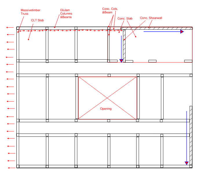
I recently had a discussion about the shear load transfer in a massive timber diaphragm. Based on my understanding from the first principles, the lateral load, wind load in this case, should be transferred to the lateral resisting elements -> conc. shear walls in this case through the collector. So here is the argument of my colleague, he is saying that the shear does not need to be transferred through a collector but it can be introduced to the shear wall from the conc slab which is positioned right below the conc. shear wall.
My plan was to use straps at each clt slab to clt slab connection and bring it back to the beam which is then bringing the force to the shear wall through some kind of a connector..
Am I being the wrong one here ? Should I throw my engineer career out of the window ?

Thanks all!
 
Replies continue below

Recommended for you

I don't see how your colleague envisions the load getting from the CLT slabs to the concrete slab?

Expanding on how I'd handle it, I'd likely have the glulam supplier design their connections to be the collectors. And then have a strap detail from the beam to the concrete shearwall on the exterior face so that it doesn't impact finish install on top of the CLT slabs or inside face of glulam. It can be hidden on the outside underneath the cladding.
 
loti_eng said:
Should I throw my engineer career out of the window ?
No, lol! Whether you're right or wrong on this (which isn't all that important anyway), you're showing the qualities of a good engineer in trying to understand this.

I agree with jayrod12. I suppose it might be possible to transfer the load from the CLT slab into the concrete slab and from there to the shearwall as your colleague suggests, but this seems like an awkward load path. I'm struggling to imagine how I'd even go about designing this. Would the CLT slab just act in tension (due to the load pulling to the left) with that tension force then being transferred into the concrete slab somehow?

Also, assuming lateral loads will need to be resisted in the other direction as well, I believe you'll need a connection between the CLT slab and glulam perimeter beam anyway to resist the diaphragm chord forces.

 
My default path would be the same as yours. That said, were I in your shoes, I would ask you colleague to prepare an FBD of the system per their conception of it. That, I feel, would give them the best opportunity to defend their idea. We're obviously biases since we're only really hearing your side of the story first hand.

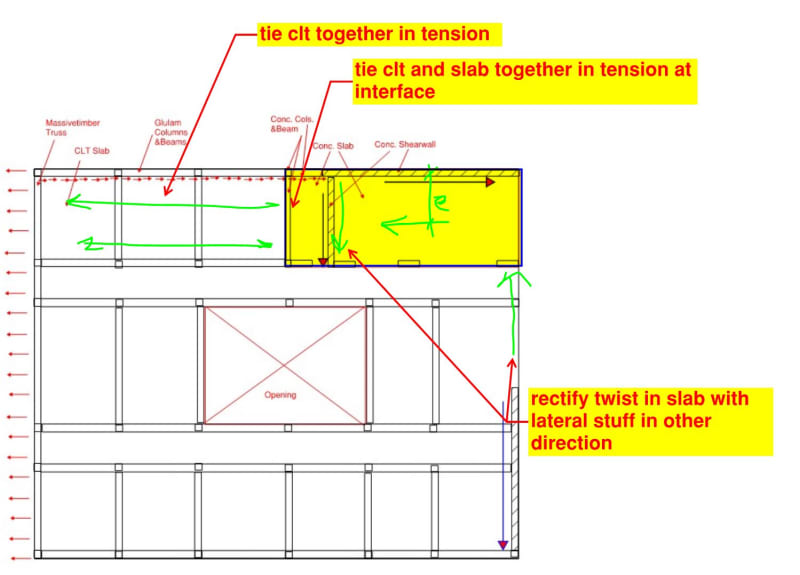
The sketch below shows one version of this that kind of sounds like what your colleague is suggesting. Effectively, it uses the CLT itself as the drag strut.

In a mixed system such as this, one might argue that the CLT should be tied in axially to the concrete slab along the entire perimeter of the slab. To do otherwise might invite some unwanted lateral separation between the floor decks where they meet.

c01_d3dhgn.jpg
 
Koot's load path would work, but the torsional moment created would be quite large and demanding on the diaphragm. Both on just the applied load, but also the torsional response given you only have one wall in each direction. Something about this is screaming circular framing.
 
jayrod12 said:
...but the torsional moment created would be quite large and demanding on the diaphragm.

Pushing this a little further for sport, I would argue that torsional moment may well be unavoidable when one considers the load reversed such that it would put the joint between decks into compression. At the least, the concrete deck would have to kind of twist out of the way some to allow the assumed perimeter drag strut to take over in the absence of a movement joint between decks.

jayrod12 said:
...given you only have one wall in each direction.

I wouldn't do this with one wall in each direction. If you examine my sketch, you'll see that I assumed lateral resistance at the right side of the concrete deck coming from a wall external to that deck which, itself, would need some manner of collector.
 
@jayrod12 he is thinking we could just tie the clt plate along the edge concrete beam with a steel angle and bolts together with the concrete slab. as Kootk indicated in his sketch, this brings an additional torsion in addition to the torsion that is already introduced to the entire slab due to the position of the walls. I actually considered concrete and clt slabs together as one piece so that I resolve the lateral loads once and introduce them to the bracing elements..
@kootk does this mean, the complete lateral force will be resolved through connectors along the edge beam between CLT & concrete slabs ?
 
I'm not sure what you mean by "complete lateral force" in your previous comment. In taking that path, one chooses a modified story telling of the lateral system. The force transmitted between the clt and concrete slab edges simply needs to be consistent with that modified story vis a vis equilibrium and stiffness considerations.
 
loti_eng, I know it's beyond your original question, but, for my own curiosity, is the entire lateral system only those 3 concrete shear walls?
 
A different view point. I've spent pretty much all my career in steel industrial structures, braced frames mostly. The notion of a floor/roof diagram is almost a foreign concept to me. If I want my floor to transfer lateral loads I generally provide discrete members to the lateral restraining system.

While this viewpoint has recently has made getting up to speed in residential construction more challenging. It also is eye opening on how ingrained in some engineers the diaphragm behaviour. It would seem that MANY engineer take it way too much for granted without a good coherent thought on how those lateral loads are transfered into the diaphragm , through the diaphragm and out of the diaphragm .

In many of my design I mostly ignore the floor diaphragm. This is certainly overly conservative, however the opposite of taking it for granted is dangerous.
 
@KootK In other words, would you then consider resolving the entire wind force along that edge - where clt connects with conc. slab ? @Eng16080 3conc. shear walls and a massive timber truss.
2_k7ibmx.png
 
loti_eng, If I understand this correctly, your only lateral resistance in the left-right direction is the concrete shear wall at the back. If that's the case, then I assume you're not relying on this LFRS to resist any seismic forces (which seems unlikely). If you did, I don't see how this would meet the requirements for "Open Front Structures", per SDPWS (see Section 4.2.5.2 for 2015 version).
 
loti_eng said:
@KootK In other words, would you then consider resolving the entire wind force along that edge - where clt connects with conc. slab ? @Eng16080 3conc. shear walls and a massive timber truss.

What other coherent load path do you propose? KootK's load path isn't the only possible load path. But you need some sort of rational load path and whatever you choose you should be confident that it suitably stiff and suitably strong.
 
it is not in the seismic zone as i indicated the latereal force as wind force. yes the wind force in x direction is resisted by the conc. shear wall at the top right edge, and the torsional moment is resolved by the other bracing elements.
 
Ok. Having zero seismic loads for a project isn't something that I'm accustomed to.
 
OP said:
@KootK In other words, would you then consider resolving the entire wind force along that edge - where clt connects with conc. slab ?

If the north shear wall is the only VLFRS in the EW direction then, yes, I would say that the connection between the CLT deck and the concrete deck ought to take all of that, direct shear. That said, some of that shear might be split into two connections:

a) That delivered to the west edge of the concrete deck.

b) That delivered to south edge of the concrete deck.
 
Status
Not open for further replies.

Part and Inventory Search

Sponsor