Eng-Tips is the largest engineering community on the Internet

Intelligent Work Forums for Engineering Professionals

Material considerations for suspension elements 2

Status
Not open for further replies.

roller_delawer

Automotive
Jan 15, 2017
13
0
0
CH
Hello everyone,

I have recently started a project to redesign the suspension elements of an existing road car and I need some advice from people more experienced in suspension parts.

The goal of the project is not to re-design the whole suspension scheme and geometry, but only the individual elements, in order to reduce weight and also (why not?) to get a more "engineering p0rn" / restomod flavour for the car.

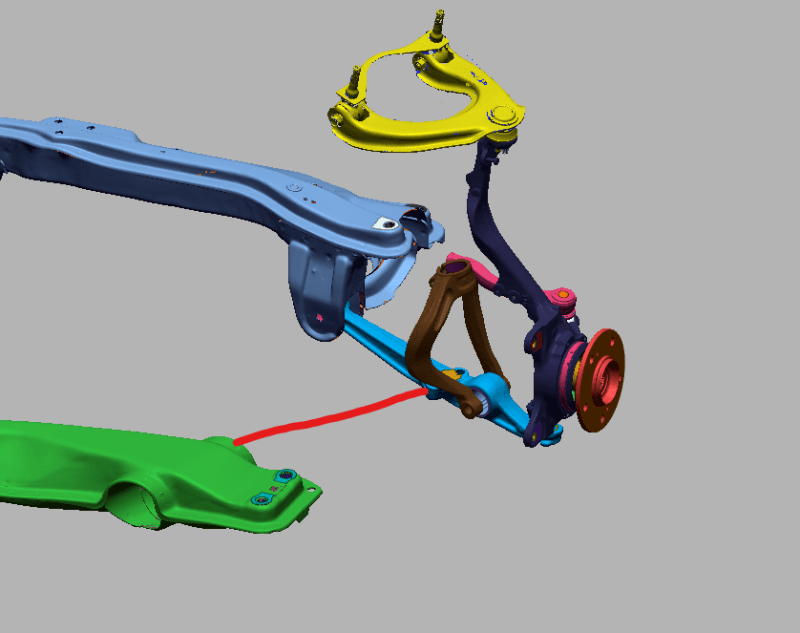
We are at the initial stages of the process, defining the concept of each component and producing the first CAD models. At this point I need to start looking at the materials and manufacturing process to draw the CAD models accordingly. All we know so far is that we want to go for CNC machined components (for the looks) but I am not sure what would be the right material choice as a starting point.

At this point is probably worth mentioning I am an experienced automotive engineer, but I have always worked with plastic/composite parts but never with metals, hence why I understand what I am doing, but need some guidance for material selection.

I reckon aluminium is probably the way to go, but I know there are several grades with highly different characteristics. Titanium has been mentioned in our internal conversations but from what I've read, it doesn't beat aluminium for this application except maybe in the "exclusivity factor". I guess steel it's probably not worth if parts will be CNC'd?

I will be very glad to hear some material advice and sources of information as well as what other considerations beyond the obvious CAE/weight/cost I should have for this parts.

Thank you very much for any possible help!

Osdecar
 
Replies continue below

Recommended for you

Thanks Greg,

Could you explain why you don't like the concept of machined arms?

And what alternative do you think is best suited then for a DIY project? Welded steel tubes, maybe?

Thanks

 
Billet has a far less suitable grain orientation than forged parts do, leaving them more susceptible to fatigue cracking.

I'll add this - for a given section steel is 3X stiffer in tension/compression than aluminum and is easily available in a similar strength to weight ratio as aluminum. Where aluminum is better is when there are out-of-plane bending loads so that a doubling of the thickness can achieve 8 times the bending stiffness at 2/3rds the weight of steel. But, as in formed suspension parts, the bending loads are converted back to simple tensile ones and the advantage usually is back for steel.

This is why welded tubular frames on aircraft are steel but thin structures like wing skins are aluminum.

So, which one is better really depends on the exact loading that is anticipated, the length of service expected, the resistance to corrosion that is desired, and if the underlying material is suitable for the application. Since there are no expectations for show cars - they like aluminum billet. It looks pretty and won't fail while parked.

The lightest suspensions are from changing the geometry of the suspension, not simply changing the material - for example as on F1 and Indy 500 race cars. But those take a lot of room.

Titanium has the disadvantage that it is about 2/3rds as strong as steel and 2/3rds as stiff. It's main claim to fame is that those miserable characteristics remain about the same at high temperatures, which is great if you are going to drive on volcanic flows, but not so useful elsewhere. Again, some special cases/geometries can be worth something, but since it sits between steel and aluminum in most regards, it's not a typical improvement over either one.

If you want some really good stuff - maraging steel. Easily machines in the typically purchased state, doesn't warp when heat treated to its top strength, which can be in the 350,000 psi yield for the right grade, and isn't brittle at the top strength. It's just rather expensive.
 
The rest of us have the disadvantage of not knowing what part of what vehicle the original poster is trying to redesign, or even a general description of what it is.

Stamped steel allows parts to be stiff in certain directions but flex in others, and some suspension designs rely on this. Then someone aftermarket decides that flex can't be good, designs a billet or tubular part or reinforcement that eliminates that designed in flex, and then they wonder why it binds up and/or breaks stuff.
 
Thank you guys for your answers,

As a general message what I get from your replies is "don't try to outsmart the OEM, they know what they are doing". And, having worked for several OEM's in the past I do agree with you.

However, despite not being a show car, the point here is trying to get an old looking car and give it a modern, lightweight, precision engineering look by doing something different from what the OEM did in the first place.


To give you more information, the car is a '91 Honda CRX and below you can see a screenshot of a 3D scan of the original parts (the red line is a reaction rod missing from the scan that connects the front subframe with the lower control arm to support braking and accelerating forces) :

IKhNyy1_e984tu.png


The main idea is to remove the 2 subframes and design 1 single spaceframe structure that connects all the mounting points, as well as redesigning the knuckle, lower control arm and upper control arm.

I'm using the accuracy of the scanned geometry to replicate the suspension in a MBS software to understand what are the loads of the OEM suspension as well as all the geometry parameters, to try to understand what was designed to do in the first place and try to replicate it in the best possible way.


Does anyone recommends some resource regarding material choice for these applications?

Thank you
 
If I remember right, that generation of Civic pre-dates the use of full subframes. The "subframe" at the back hangs onto the inner ends of the lower lateral links and has the steering rack (not shown) attached to it. The driveshaft (not shown) also sneaks through there, through the middle of the hole in the brown bracket and I think it passes in front of that whole subframe. The front crossmember (green in your illustration) supports the trailing links, which intentionally have soft bushings for NVH isolation. The front antiroll bar (also not shown) also connects in there somewhere. The engine mounts go to the unibody because there's no full subframe. The soft bushings in the trailing links are meant to have minimal effect on the handling, because the lower lateral link and the steering tie-rod form a parallelogram, so slight fore/aft movement of the knuckle due to bump impacts have little effect on the steering. The various connections between the lower lateral and trailing links and that funky-shaped strut bracket have to accommodate the various twists and turns of all this as it goes up over bumps, and as it gives way a little bit from fore-aft bump impacts (or acceleration or braking forces). Hence ... bushings with some give to them.

This is a highly optimised design from the OEM. It, and the unibody around it, is also safety-critical. Speaking from observation (cars broken at the side of the road ...) if the lower ball-joint fails (and it's under tension from the weight of the vehicle, which does not help matters) the whole thing collapses. It isn't perfect. The MacPherson design that Honda used before this, and then switched back to a few years later, doesn't put the vehicle's weight through the ball-joint in tension.

I know this platform has had more than its share of aftermarket support over the years. Begs the question ... what are you trying to do, that hasn't already been tried?

My dad, once upon a time, had cars with a cousin of this suspension design (1986 and 1989 Accord), and I remember them having very good ride and handling for their day, if perhaps a little softly sprung.
 
OEM material, treatment, and coating specs are commonly available in their component design guides. Motorsport regulating bodies will also have their own guides.

If your goal is to end up with an improved suspension then I would highly recommend spending a few thousand on professionally designed and validated aftermarket parts for safety/liability reasons alone. CAD & MBD are no replacement for experience with both system design and vehicle fabrication techniques. What you're proposing is far more complex than producing a prettier/stronger control arm, altering your limp-noodle chassis' stiffness can have a significant impact on everything from geometry to strength requirements so Honda's original design is irrelevant.
 
Status
Not open for further replies.
Back
Top