Continue to Site

Eng-Tips is the largest engineering community on the Internet

Intelligent Work Forums for Engineering Professionals

  • Congratulations KootK on being selected by the Eng-Tips community for having the most helpful posts in the forums last week. Way to Go!

Max weld size on tube sections 4

Status
Not open for further replies.

Veer007

Civil/Environmental
Sep 7, 2016
379
i have to weld 3/8" size of fillet weld to (HSS6X6X1/4) 1/4" wall thicknes of HSS, as far as i know the weld size must not exceed (D-1/16") where D is wall thickness, But there is a table (3-46,90° fillet size to develop wall strength) shown in CISC handbook says larger weld size, Anyone have encounterd this type of case? advise

Thanks in advance!!
 
Replies continue below

Recommended for you

The maximum weld size is for welds placed on the edge of the tube thickness, not on the side of the tube. So the orientation of the weld matters.

Check out Eng-Tips Forum's Policies here:
faq731-376
 
thank u..

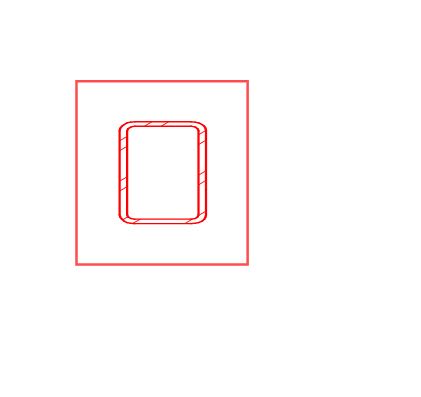
Do u refer me any pics,if possible? i have to weld hss column on base plate
Capture_uafyxn.jpg


Thanks in advance!!
 
Well...I would say weld size can be maximum thickness of the tube section
Plate need to be thick enough

So the welded connection can have the full capacity of the section
Weld need to be inspected after welding
 
You can use a 3/8" fillet between the 1/4" wall tube to a plate. Why not? How much of the tube do you need to develop? A 1/4" fillet won't develop the full tube capacity.
 
For a fillet weld, the base material thickness must be a minimum of 3.09D/Fu per equation 9-2 in the AISC 14th edition steel manual.
 
To add to Stenbrook's comment, you CAN put whatever size fillet weld you want on. Just know that there is a point where increasing the weld size WON'T increase the capacity to transmit forces, due to the shear failure of the base material (i.e. the formula that Stenbrook posted).

Ex: Assuming A500 Gr. C (Fy = 50 ksi, Fu = 62 ksi), the maximum weld size (in 16th's of an inch) that can be developed is

t_des * Fu / 3.09 = 4.67 16's of an inch (so, a 1/4" fillet weld won't develop the full strength, and the 5/16" fillet will develop the full strength of the section, but you'll need to limit your force transfer to the capacity of the tube, not the weld strength)

where
t_des = 0.93 * 1/4" = 0.2325
Fu = 62 ksi
 
Equation 9-2 is setting base metal shear rupture equal to weld shear rupture. Suppose the tube is in pure tension? Here's something I came up with a few years ago.

The required fillet weld size is determined by setting the tensile strength of the wall equal to the strength of the weld and solving for the fillet leg size (w).

Tensile strength per unit length of HSS wall:

ΦtFyt
Where,
Φt = resistance factor (0.9)
Fy = specified minimum yield stress
t = HSS wall thickness

Strength per unit length of fillet weld:

Φ0.6FEXX(1.5)(0.707)w

Where,
Φ = resistance factor (0.75)
FEXX = filler metal classification strength (use 70 ksi)
w = fillet weld leg size

Note that a 1.5 factor is included since the force is applied at a 90° to the weld. Oddly, this increase in strength is not allowed when using Chapter K of AISC 360-10 when sizing for applied loads, causing the Chapter K method to be less economical for members with appreciable loads.

Setting these two equations equal and solving for w when Fy=50 ksi we get,

w=1.35t

So, in the example above we would get w=1.35(0.2325") = 0.314" or 5.02 16ths versus 4.67 16ths from above, which is still 5/16" fillet weld unless you're super anal and would round up 5.02/16" to 3/8".
 
dozer,
For a pair of welds on two sides of the tube, perhaps the 1.5 factor applies.

But both 360-10 and 360-16 state in the User Note that a "linear weld group" is on in which all elements are in a line or parallel.
For a square tube weld layout, you don't have that so technically the 1.5 factor doesn't appear to apply.


Check out Eng-Tips Forum's Policies here:
faq731-376
 
JAE,

Is that the rationale for not using the 1.5 increase? I don't use it because chapter K says not (and have it dinged on outside review before), but I never understood why. I guess according to the letter of the specification it makes sense, but how does the weld know if it's in a square or just in a line?
 
The last paragraph of the section containing equation 9.2 (Connecting Element Rupture Strength at Welds)states that there is no limit on fillet weld size when one element is subject to tensile force and is not in the plane of the element being connected. One example is wall of HSS to base plate. In these cases the fillet weld need only be sized to resist the tensile force and a base metal check is not required.
(15th ed. page 9-6).

All I know is P/A and Mc/I
 
JAE said:
But both 360-10 and 360-16 state in the User Note that a "linear weld group" is on in which all elements are in a line or parallel.
For a square tube weld layout, you don't have that so technically the 1.5 factor doesn't appear to apply.

winelandv said:
Is that the rationale for not using the 1.5 increase? I don't use it because chapter K says not (and have it dinged on outside review before), but I never understood why. I guess according to the letter of the specification it makes sense, but how does the weld know if it's in a square or just in a line?

JAE is referring to J2.4(a) which applies specifically to linear weld groups, however J2.4(c) may be used for concentrically loaded weld groups consisting of longitudinal and transverse welds. It is permitted to increase the strength of transverse welds provided we discount the strength of longitudinal welds, R[sub]n[/sub] = 0.85 R[sub]nwl[/sub] + 1.5 R[sub]nwt[/sub].

For connections to HSS my understanding is that it's not permitted for a couple reasons:
1. The effective weld length equations over time have evolved so as not to consider the 1.5 increase.
2. Testing has shown the 1.5 increase to provide adequate safety factor for some conditions but not others.

McFadden & Packer offer this explanation (Link):

The (1.00 + 0.50 sin[sup]1.5[/sup]θ) factor (or fillet weld directional strength enhancement factor) should not be universally applied to all connections between HSS, when the effective length method is used, because it may result in an unsafe design. This may be because connections with HSS are inherently eccentrically loaded (because welding can only be performed on one side of the branch wall) and secondary effects create additional tension at the fillet weld roots.
 
If the member in question were a wide-flange column in lieu of an HSS and the connection was subject only to moment to keep the discussion simple, would AISC 360-10 (or AISC 360-16) permit a load direction strength increase (1.5, since Θ = 90 degrees) for a fillet weld connecting the column to the base plate? I thought the answer was "yes" but JAE's response above is giving me pause. AISC 360-10 Commentary Section J2.4 addresses the validity of applying the load direction increase to out-of-plane load conditions and it seems to me the weld would not 'know' if it were loaded transversely in-plane or out-of-plane.
 
Fairly recent testing has shown that the 90 degree factor doesn't hold for HSS connections and that a failure occurs at around the 0 degree shear value. I'll try to track it down later.
 
In 2016 I sent a question to AISC regarding strength of welds on HSS members. While the responder did concede that there are some individuals who assert that the AISC specification prohibits the use of the directional strength increase with HSS, he said that that view was not generally held by the specification committee, though there had been no formal vote. His feeling was the 1.5 increase could be used for sizing a weld connecting a HSS member in tension.

In 2017 I asked another related question and within the response he said that the directional strength increase for HSS connections was continuing to be investigated but his position had not changed. Maybe things have changed since then but that was the last word I got on the subject.
 

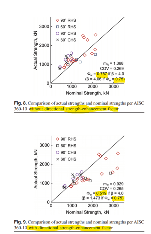
The journal article above has testing results for HSS to plate connections where the weld is the critical failure point. The HSS was then loaded to connection failure in tension.

Basically, they found that when you try to use the directionality provisions in the US and Canadian codes for HSS with a perimeter weld, the level of reliability ends up being significantly less than intended.

To get the reliability that the code says it's trying to achieve, the capacities you get using the provisions for 90 degree loading would need to be multiplied by 0.62 for CSA S16-14 and 0.69 for AISC 360-10. I back calculated these values by comparing the code mandated phi factor for welds to the effective phi factor that their study determined was necessary to meet the code target reliability goals.

The attached image shows the testing results compared against AISC 360-10 calculated values. The nominal calculated strength is the strength prior to application of the phi factor. They then calculated the effective phi value that would need to be applied to reach the reliability index (beta=4.0) that the code uses as a target.

If you use the non-directionally amplified capacity calc, you basically get the reliability that the code wants. If you use the directionally amplified calc in this situation, you get significantly less.

Annotation_2019-03-28_195613_d0zhtm.png


The Eurocode calc method did pretty well.

CSA S16-14 is frustrating because they let you go even higher with the directionality capacity amplification than the previous revision but then hid a note in the code appendix saying that you might want to think about whether you want to use it in this situation based on recent research. Not even a uses note in the code body, when they obviously realized there was an issue. I can guarantee most people aren't noticing that.
 
Status
Not open for further replies.

Part and Inventory Search

Sponsor