Continue to Site

Eng-Tips is the largest engineering community on the Internet

Intelligent Work Forums for Engineering Professionals

  • Congratulations IDS on being selected by the Eng-Tips community for having the most helpful posts in the forums last week. Way to Go!

Maximum Circuit Lenghth Help

Status
Not open for further replies.

Mbrooke

Electrical
Nov 12, 2012
2,546
I have a few questions regarding this table from page 4 of this PDF:
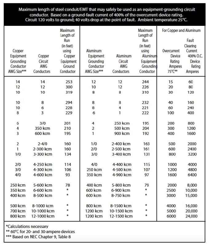


Max_Z_ikrre9.jpg


1) Why settle on 400% current as the minimum allowable short circuit current? Time current curves of fuses and breakers indicate that current at 4 times the rating takes about 30-50 seconds to clear. Id imagine sputtering or arcing would increase this time.

Reference time current curves:


Would this time not be a fire and shock hazard, especially at on circuits 30 amps and below?

2) Why do they list short circuit currents at 80% of what chapter 9 table 9 indicates?

3) Why do sizes 350kcm and above require calculations? And if so what type/kind of calculations?
 
Replies continue below

Recommended for you

I'm guessing that the Steel Tube Institute wants you to use the steel conduit as the EGC, which is a terrible practice that should be banned, IMO. The headings in the table are misleading. The lengths are referring to maximum length of CONDUIT that may be used instead of the CU or AL EGC. The NRC gives no maximum length for EGCs. It does say that if the phase conductor size needs to be increased for voltage drop, then the EGC size must be increased a proportional amount.

The 400% may relate to the NEC methodology in coming up with the EGC size in the NEC table. But if you're following the NEC, it doesn't matter.

 
I'm guessing that the Steel Tube Institute wants you to use the steel conduit as the EGC, which is a terrible practice that should be banned, IMO.

FWIW, I can agree here.

The headings in the table are misleading. The lengths are referring to maximum length of CONDUIT that may be used instead of the CU or AL EGC. The NRC gives no maximum length for EGCs. It does say that if the phase conductor size needs to be increased for voltage drop, then the EGC size must be increased a proportional amount.

Right, but the table lists a maximum EGC. When I crunch the numbers I get exactly 80% of the current values listed in the table. Basically the first table assumes plastic conduit with a wire EGC. At least thats what the math is telling me.


The 400% may relate to the NEC methodology in coming up with the EGC size in the NEC table. But if you're following the NEC, it doesn't matter.

It would matter though, beyond a certain length a breaker will not trip. 400% will trip a breaker, but that number seems absurdly low.
 
On a very long circuit 400% may be all the current available to trip the breaker.
Consider an LED lamp a long way away.
Minimum current so no need to increase the conductor size.
At some distance you may have a code compliant installation that will not trip a breaker in a reasonable time, if at all.

Bill
--------------------
"Why not the best?"
Jimmy Carter
 
Right, I fully agree. But I am curious why the paper picks 400% instead of say 800%? I could understand 5 seconds, even 10 seconds... but beyond that I'd say you are really pushing a dangerous situation it.
 
Forget that table and do something productive, Mbrooke.
The steel tube institute can do all the calculations that they want, but they are ignoring reality.
Conduit and EMT are bad grounding conductors.
Over time the joints lose continuity.
What was a good connection on the day that it was installed may be a high resistance path or an open circuit after 10 or 20 years.
Do you remember the isolated ground circuits?
A couple of other issues with that table.
Conduit is equated with EMT.
Same material, different cross sectional area.
No indication of the rating of the over current device for a given conductor size.
No indication of the temperature at which the conductor ampacities are taken.
No indication of the type of load.
A general load at 16 Amps may have a 20 Amp breaker, a motor at 16 Amps may have a 40 Amp breaker.
We have wasted too much time on that table as it is.

Bill
--------------------
"Why not the best?"
Jimmy Carter
 
For long circuits, the phase conductors will generally need to be increased in size due to voltage drop. This requires the ground wire size to be increased as well. If you don't have one, I'd suggest purchasing an NEC HANDBOOK from NFPA. It contains all of the NEC text but also a lot of background on how some the NEC requirements were developed.
 
Respectfully, dpc, I agree with you for almost all circuits protected at 20 Amps and above.
15 Amp circuits may be at times an exception.
If one of my rural neighbors who has a driveway about 1/4 mile in length wants an LED lamp to mark his turn off of the highway, we can see the exception.

Bill
--------------------
"Why not the best?"
Jimmy Carter
 
Bill,

Agreed. Maybe convince him that he needs to install a GFCI breaker. :cool:
 
Forget that table and do something productive, Mbrooke.
The steel tube institute can do all the calculations that they want, but they are ignoring reality.
Conduit and EMT are bad grounding conductors.
Over time the joints lose continuity.
What was a good connection on the day that it was installed may be a high resistance path or an open circuit after 10 or 20 years.

I can agree here for the most part. But again, it stems from the fact NEC does not define "effective ground fault current path"


Do you remember the isolated ground circuits?
A couple of other issues with that table.
Conduit is equated with EMT.
Same material, different cross sectional area.
No indication of the rating of the over current device for a given conductor size.

Look at the table again- "over current device amperes 75*C" In addition to the current value (400%) they believe qualifies as an EGC path.


No indication of the temperature at which the conductor ampacities are taken.

75*C

I can confirm that when I crunch the number from chapter 9 table 9 they all come out at 125% of the 400% current listed on the table went put through ohms law.

No indication of the type of load.
A general load at 16 Amps may have a 20 Amp breaker, a motor at 16 Amps may have a 40 Amp breaker.

For the most part it does not matter when dealing with short circuits.

We have wasted too much time on that table as it is.

What would you say is an acceptable breaker disconnection time?
 
For long circuits, the phase conductors will generally need to be increased in size due to voltage drop. This requires the ground wire size to be increased as well. If you don't have one, I'd suggest purchasing an NEC HANDBOOK from NFPA. It contains all of the NEC text but also a lot of background on how some the NEC requirements were developed.

Does the NEC Handbook actually define an effective ground fault current path in numbers? Simply saying "to open an OCPD" means nothing.

Bill,

Agreed. Maybe convince him that he needs to install a GFCI breaker.

GFP breakers are great, that is until they fail. GFCIs, GFPs and RCDs are a backup, not the primary mode of protection.
 
Quote:
No indication of the type of load.
A general load at 16 Amps may have a 20 Amp breaker, a motor at 16 Amps may have a 40 Amp breaker.


For the most part it does not matter when dealing with short circuits.


So I have two circuits running to the same location, both #12 AWG copper.
One circuit supplies a general load and is protected by a 20 Amp breaker.
The second circuit feeds a motor and has a 40 Amp breaker.
The short circuit current may be the same but the breaker size is not.
400% of 20 Amps is 200% of 40 Amps.


Bill
--------------------
"Why not the best?"
Jimmy Carter
 
Agreed. Maybe convince him that he needs to install a GFCI breaker.
Good idea.
At the least I would install a local grounding electrode and locally ground all exposed conductive parts.
I just installed a small panel with a couple of receptacles for a neighbour.
The issue was not the length of conductors but local grounding where an overhead line transitioned to an underground line.
(A long way from the transformer and meter to the house.)
The original installation was not compliant as the junction box at the transition and where I installed the sub panel had no ground for the JB.
It does now.


Bill
--------------------
"Why not the best?"
Jimmy Carter
 
So I have two circuits running to the same location, both #12 AWG copper.
One circuit supplies a general load and is protected by a 20 Amp breaker.
The second circuit feeds a motor and has a 40 Amp breaker.
The short circuit current may be the same but the breaker size is not.
400% of 20 Amps is 200% of 40 Amps.

Right, however the table lists the OCPD.


Good idea.

GFCIs are not reliable and fail. Its this logic thats literally putting more and more GF protection into the code.
 
Is there a date on that table?

Bill
--------------------
"Why not the best?"
Jimmy Carter
 
GFCIs, GFPs and RCDs are a backup, not the primary mode of protection.

Says who? They are absolutely the primary mode of protection against electrocution. In general, the NEC is a FIRE protection code. If you are concerned about shock hazards, then normal overcurrent devices are not the primary protection.
 
That 1/4 mile circuit won’t stay on with a GFCI breaker at the source end.
 
Totally off topic - do you have a side gig Dave? Looking at a “Mid-Willamette Valley Food Trail” map and I see a “Castor Kitchen and Bar” in downtown Corvallis.
 
Status
Not open for further replies.

Part and Inventory Search

Sponsor