Eng-Tips is the largest engineering community on the Internet

Intelligent Work Forums for Engineering Professionals

  • Congratulations waross on being selected by the Tek-Tips community for having the most helpful posts in the forums last week. Way to Go!

Measuring Sheet Angles & Flanges 4

Status
Not open for further replies.

Sparweb

Aerospace
May 21, 2003
5,103
0
36
CA
Just a quick question about the basics. Is there another way? A better way?

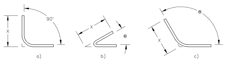
Here are 3 common sheet-metal angles. To inspect the angles, the length of each flange is often found to be specified on the drawing as "X" at angle "Ø", and usually 90 degree angle is just implied.

Sheet_Bend_Measurements_sc8l0c.png


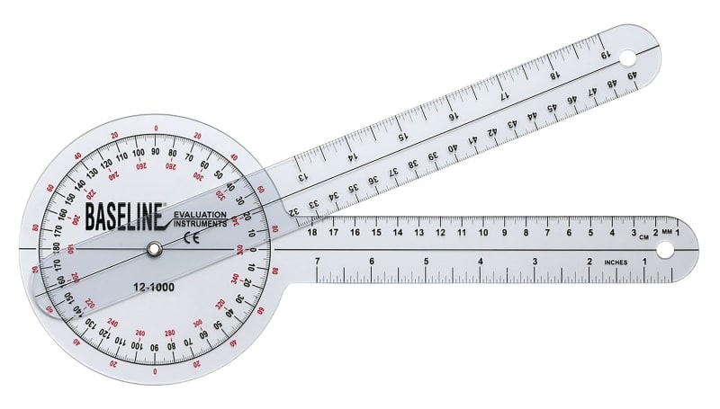
The 90 degree angle is normally measured with a square. With the protractor set like the one shown below, I'll be able to measure either the acute or obtuse angles and length of each flange.

Starrett_Protractor_jjv32p.png


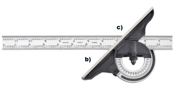
I do notice that in the process of measuring either the acute or obtuse angles, I will have to adjust the ruler slide until one of the marks lines up with the intersecting edge of the protractor's bevel. Not a big deal, but it's an adjustment repeatedly made, it varies anywhere the angle varies, and it's just done by eye. I haven't questioned this before, but after explaining this process to someone else recently, I've started to wonder:

Is there another method or tool to measure these angles?
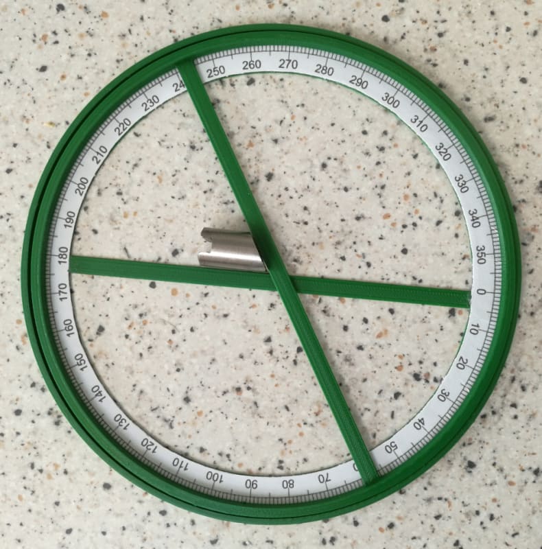
 
Replies continue below

Recommended for you

Measuring to the "heel line"="mold line" like that is pretty annoying when someone slaps ±.01 or worse ±.005 on a print.
One of my biggest customers will FARO arm scan parts and send me a full blown report(do the same thing for rigid tubing).
I use a CMM with pc-dmis to check incoming parts to me with annoying tolerances. Not annoying sheet metal parts= ±1/32 to ±.1 it's pretty easy to use a combination square. I have a forged Starrett set I really like that has 100ths. End of the day, It definitely makes the cleanest prints dimensioning to heel line.

Also I have a lot of customers fully dimension a flat pattern which is really annoying, because if they didn't work with us from the get go, nailing the actual bend radius, knowing actual material thickness, without fail they will over define the part by calling out end of a leg to the outside of the bend... That usually results in a rev. But I know why they do it because... that's what I end up doing internally:

On the actual shop floor I have to break things down for the operator, we will in progress inspect the flat pattern off the router/laser/turret punch. **Usually** there is geometry on a flat part that directly fits against the pressbrake back gage, then we set and check the pressbrake back gages with traceable means (calipers, dial gage), usually my pressbrake operator only sets the backgage and checks angles. So my internal prints/instructions are based off of that dimensioning concept and includes the ID# for specific bottom dies/tool holders, and top punches that I know when set generates a R.127 with a .42 k factor in 1/4 hard 0.080" thick 304 with laser film on one side. 20% of the time I have scrap, it comes down to a bad back gage set up. The other 75% of the time, they bend it backwards/upside-down. The last 5% is nutty stuff like wrong stock, loose punches, machine out of level after getting backed into by a forklift...

That said... I also have plenty of "functional check" parts where we grab a mating part. Nothing wrong with that as long as the process is documented and it works.
 
SW...

You have the pretty angle-gage... I have a clunky/shop version [no Vernier, just degree marks]

That's how I would normally do it.

Otherwise... optical comparator or digital scan to a CAD file... then 'CAD-trace' the edges and ask for the angle.

Of course... for production/real-world... measure multiple locations. AND You will need to take into account the design/drawing tolerance [+/-1-deg Typ] for sheet metal fab.

war story. One of the funniest encounters I ever had with a young/new designer was with sheet metal angles, while he translating an old [1950s era] hand-drawn [vellum] flap-design to CATIA. The flap assembly drawing had a very slight taper that demanded a flange angle of ~90.3-deg... but the detail drawing for the 0.040 thick formed rib flanges was 90.0-Deg. Period. He couldn't make the ribs fit the model. I had to explain old-fashioned 'hand-fitting' methods allowed by [thin] sheet metal 'flexibility'.

Regards, Wil Taylor
o Trust - But Verify!
o We believe to be true what we prefer to be true. [Unknown]
o For those who believe, no proof is required; for those who cannot believe, no proof is possible. [variation,Stuart Chase]
o Unfortunately, in science what You 'believe' is irrelevant. ["Orion", Homebuiltairplanes.com forum]
 
Given the rise of 3d printers one could just print a couple of "inspection" gauges (depending on the accuracy required, measure the gauge first and call them a comparitor). It might also actually work for repairs as well.
 
badservo… 18 Nov 21 19:57... elegant/sweet!

Regards, Wil Taylor
o Trust - But Verify!
o We believe to be true what we prefer to be true. [Unknown]
o For those who believe, no proof is required; for those who cannot believe, no proof is possible. [variation,Stuart Chase]
o Unfortunately, in science what You 'believe' is irrelevant. ["Orion", Homebuiltairplanes.com forum]
 
Thanks for all the feedback, everyone!
I'm always pleasantly surprised by some of these "back to basics" questions - when asked to share experience this great stuff always come up.

RoarkS, thank you for the production point of view. My needs rarely venture into the level of detail you face, and your efforts to make the process more robust will remain in my mental "toolbox".

Wil,
I do have my own Starrett protractor and combo square, but I sometimes see people on my manufacturing floor using lesser tools. Since they're in production and I'm not, there's a reluctance on my part to step in and suggest they get more expensive tools.

Badservo,
OMG I have to get/make one of those. :) Guessing I could slip a 2" wide part right through and have the angle in seconds. I'd prefer a more robust version, but now that I've seen what I'm looking for, I'm sure I can turn up a variation. And I have the CAD tools I need to alter this design to my needs PLUS friends with FDM printers, too...

Most sheet-metal drawings I produce apply a standard drawing tolerance of +/- 0.03" and I keep most flange dimensions to 2 decimal places, so that nobody gets and grand ideas about accuracy. The angles themselves get a +/-1 degree tolerance. Considering the "hand-fit" done on most assemblies, I think Wil's point still holds.

Ideas coming to mind: The ideal tool would be one that has the center of the protractor at the vertex of the intersecting straightedges. The tool that I posted, and those posted by MintJulep, all have the protractor center offset from the straightedges. That's why the ruler has to be adjusted every time you move the angle. The tool posted by Badservo fixed that - but encloses the protractor in a ring, limiting the size of the part it can measure. Sure, print a bigger one... but I think I have an idea that will do the same, but not need an external ring...

Getting out my sketchbook...
 
That leads me to find the "goniometer". For some reason the linear scales do not have graduations starting at the vertex. Nor can a part be aligned with respect to the goniometer's vertex, either. The vertex isn't really of interest on this tool, it seems.

Goniometer_jgvdms.jpg


This could also be used to find the angle, but it can't give you the flange length measurements.

Goniometer_digital_box_qqnxfa.jpg
 
Sparweb

it depends on the size of the parts (product),as a previous precision mechanical inspector, it will depend on the tools at hand and what the precision required by the customer.
for non critical, very liberal tolerance parts ya that would work as stated before. CMM would be a good choice. for simple, small lots, height gage and sin bar on a surface plate.
and for quick checks if it fits optical comparator. with graduated linear and angular Mylar. as stated before and I gave a star go * no go gages for a large quantity.
 
Agreed, a sine bar on a surface plate would be extremely accurate way to measure the angle. The surface plate also suggests that measuring the flange length from the vertex can also be done very accurately, with an additional tool setup.
 
Status
Not open for further replies.
Back
Top