Continue to Site

Eng-Tips is the largest engineering community on the Internet

Intelligent Work Forums for Engineering Professionals

  • Congratulations KootK on being selected by the Eng-Tips community for having the most helpful posts in the forums last week. Way to Go!

Mechanical Linkage?

Status
Not open for further replies.

feensm

Mechanical
Apr 3, 2019
2
Hello All,
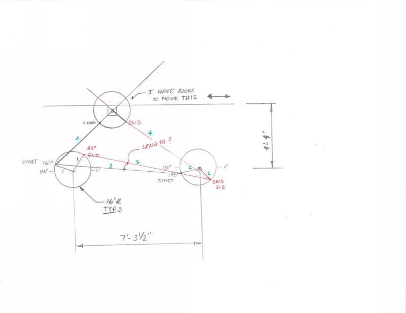
I am trying to design a linkage system to close and open a bypass plate that weights roughly 200lb. I have two fixed points of rotation and the arms are the same length. I don't understand why the bar between them is not the same length at start and end point of the rotation when they are complementary angles. Can someone explain what I am not thinking about. This lever will be operated from the deck above
Linkage_Sketch_uwph5i.jpg


This is myh first time ever designing something like this as you can tell I'm sure. I am stuck and don't know where to go.

Thanks
I appreciate the help
 
Replies continue below

Recommended for you

Linkage_Sketch_c57wbk.jpg


fixed where bar 4 is at the end of rotation.
 
where are the fixed points? follow standard drawing procedures to identify those fixed points.
 
also identify the force that move the linkage by a letter and arrow to indicate the direction of the force and the load point also by letter and arrow showing the direction of the load
 
feensm said:
I have two fixed points of rotation and the arms are the same length. I don't understand why the bar between them is not the same length at start and end point of the rotation when they are complementary angles. Can someone explain what I am not thinking about.

I assume the fixed points are the centers of the circles, and that you are referring to the length of bar 3. The horizontal component of the length doesn't change, but the vertical component does.


pylfrm
 
You can certainly achieve complementary rotation angles of the two shafts but only when these angles are symmetric around a plane perpendicular to where bar 3 is tangent to the two crank radii.
So the start/stop angles 195, 315 and 45, 165 will change then.
If that is acceptable there is a solution.
Plus it might be needed to fix bar 4 not to the same node as 1 and 3 are connected.
Hope this is clear!
 
"...I assume the fixed points are the centers of the circles..." Never assume anything in engineering work and paraphrasing my old thermodynamics teacher asumes makes an "aaaasss" out of "U" and "me"
 
To clarify my first post: Shorten link 3 so that both cranks 1 and 2 are perpendicular to link 3. That position will be the center position of the mechanism from where it can swivel left and right.
 
Knowing the length of the original link 3 starting at 165 deg and ending at the 95 deg angle of the second circle (bottom right), then draw an arc whose center is at 45 degree of the rotated link 3 with a radius of the length of link 3. The arc may or may not intersect the second circle (bottom right). If it intersect that second circle than that or these intersection point(s) will undoubtedly be other than at the 315 degree angular position shown in your sketch. It is conceivable that the arc may intersect that seoond circle at two or more points so a decision needs to be made by you. If the 315 degree angular position on that second circle is vital than use it as a center point for another arc of the same radius of a length of link 3 and have that arc intersect the circle on the bottom left to determine the position of the rotated link. Link 3 then will have the same length at those two positions.
 
Upon reviewing your drawings, I realized that the three circular paths will intersect and overlap. Some dimensions are off
 
Status
Not open for further replies.

Part and Inventory Search

Sponsor