Eng-Tips is the largest engineering community on the Internet

Intelligent Work Forums for Engineering Professionals

Member slippage/ bolts in bearing? 10

Status
Not open for further replies.

DJL Eng

Mechanical
Nov 9, 2023
14
0
1
US
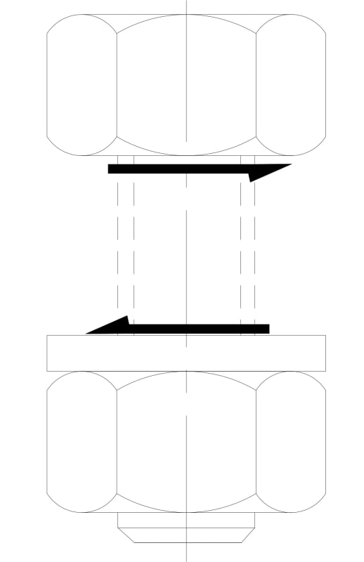
I am trying to determine bolt stresses from a resulting shock load. A component is bolted to a mounting plate and the mounting plate is bolted to a fixed structure (see attached sketch). The system sees some acceleration due to shock. We cannot bolt the component directly to the structure since it would require significant modifications and a design change (negative impacts to cost, schedule, yada yada...). Assume symmetrical loading, bolt patterns, and components. The qty. 12 bolts sit in counterbored holes to prevent contact with the component.

I am mainly concerned with the stresses in the qty. 12 mounting plate bolts. I determined that the bolts are sized such that a preload could be applied to provide sufficient clamping force (thus friction) to prevent slippage of the members. I then treated this like a cantilevered beam and the fixed end is the mounting plate bolted connection. So, due to symmetry of loading and geometry, I assumed half (qty. 6) of the bolts would be in tension. I only solved for stresses due to tension in these bolts after finding bolt/member stiffness.

A coworker of mine says that I should account for shear as well. He says that due to possible variations in workmanship, the bolts could be in bearing when installed and the clamping force would not help in this case. I disagree, but I have been wrong before; what do you guys think?
 
 https://files.engineering.com/getfile.aspx?folder=83bb3f43-d75e-406b-8f66-0b91c16c2653&file=20240118_085408.jpg
Replies continue below

Recommended for you

Thanks for that link; it's a good read. The shock load is not cyclical. Currently the mounting plate does not use alignment aides.

It still seems that if I apply a preload to apply an adequate counteracting friction, then the 'critical slip distance' wouldn't be achieved.
 
You should not count on friction to carry loads. You should check the bolts and plate bearing strength for the applied shear loads; probably reasonable to assume even distribution of bolt loads.
 
Hi DLJ Eng

I agree with you, if the bolts are pretensioned so that relative movement between the clamped plates cannot occur then the bolts won’t see any shear. Consider that all the 12 bolts are concentric within the bolt clearance holes, if the plates can’t slide the bolts don’t see any shear. Now with the preload identical as before but with only six bolts concentric in the bolt holes and the remaining six bolts in contact with the side of the clearance holes how would the bolts see shear if the plates can’t slide?

That said, I would ask how confident you are that the bolt preload is sufficient to prevent relative movement between clamp plates because friction is usually highly unpredictable?
Your co-worker is correct if the plates can move.

A final question if I May is why have you used twelve bolts when original device base plate only has four?

“Do not worry about your problems with mathematics, I assure you mine are far greater.” Albert Einstein
 
@desertfox

For coefficient of friction, I used the worst-case values from my Machinery Handbook. However, I see your point. Friction values can vary wildly and without any testing or historical data I won't actually know the coefficient of friction. Lastly, the component is an existing device and came with 4 mounting holes and another thing we cannot modify. To be honest, I do not know the exact reason 12 bolts were selected for the mounting plate. I know their locations are driven by the fixed structure geometry underneath. If I can prove that 12 bolts are excessive, we could reduce the number of bolts. Luckily, we can change the mounting plate design.

Btw, the mounting plate is really more like a bracket since it has material removed to cut down on weight. I just got lazy in my sketch.

 
Hi DLJ Eng

Are the four bolts for the original device a larger size than the ones you are proposing for the twelve bolts?
Also if you need twelve bolts to prevent slippage on the structure what about the slippage between the component and your mounting plate? The component only has four bolts to prevent slippage or am I missing something?

“Do not worry about your problems with mathematics, I assure you mine are far greater.” Albert Einstein
 
Here is a little more discussion on slip-critical bolting from the structural point of view.

There is quite a bit of discussion in the Specification for Structural Joints Using High-Strength Bolts Maybe see what is stated regarding faying surfaces and friction.

Are these tapped holes? What are the materials? From the sketch it looks like you may have some fairly short bolt grips with a good chance of loss of tension for a slip-critical connection.
 
"check the bolts and plate bearing strength for the applied shear loads; probably reasonable to assume even distribution of bolt loads."

"due to possible variations in workmanship, the bolts could be in bearing when installed "

I'd say in a pattern of 16 bolts in clearance holes if the plate slides in one direction until resisted by the bolts ( and whatever restrains them in the lower component) the likelihood of more than 4 or 5 bolts being loaded in shear is highly unlikely.


Then if the load changes direction, those 4 or 5 bolts may not be loaded in shear at all.
Other bolts in the pattern will have to man up.
 
Thank you for the replies everyone. There is only one other mechanical engineer to discuss this with at my job, so it's really nice to receive these different inputs.

@desertfox

I am not sure what you mean by the "original device", but I assume you are talking about the "component" in my sketch. The mounting plate will not replace the mounting method of the component. It is just intended to connect the component to the fixed structure. A better noun name for the plate would be "Adapter Plate". I hope that helps. I apologize that my sketch is not very clear. The 4 bolts are 7/8-9UNC and the 12 bolts are 3/8-16UNC. For a little more context, the situation depicted in the sketch is a testing arrangement. When the component is mounted on its actual structure, it will not have a mounting plate. The 7/8-9 UNC bolts will be torqued to the same value in either scenario, but now I am questioning that due to potential differences in friction between the faying surfaces of the actual assembly and test assembly.

@dvd

Thank you so much for those links. I definitely did not have adequate appreciation for what it takes to achieve an adequate slip-critical joint. All holes are through holes. The fixed structure and mounting plate are 5086 aluminum and the component base plate is some high strength steel. I'm blanking on what the steel class is.

@Tmoose

If I understand correctly, you are saying in a symmetric pattern of 16 bolts, it is unlikely that they are evenly loaded in shear (given my loading scenario) even if you assume good GD&T and installation of bolts? That calculator you linked is awesome BTW.
 
I was thinking the same as TMoose,
The first time that this slips only a portion of the bolts will be loaded in shear.
As bolts and/or the holes distort them more of them will come to bear.
I can't see why you would need so many bolts in the baseplate.

= = = = = = = = = = = = = = = = = = = =
P.E. Metallurgy, consulting work welcomed
 
Hi DLJ Eng

What I aiming to say is the adaptor plate with the 12 bolts which you are pretensioning to prevent it from sliding on the main structure and yet you are relying on 4 bolts to prevent sliding of the component on the adaptor plate and that’s without considering the flying surfaces which are clamped together.

Perhaps a better way of putting it would be:- will the four bolts on the component be sufficient to prevent it sliding on whatever it is mounted on.

“Do not worry about your problems with mathematics, I assure you mine are far greater.” Albert Einstein
 
@EdStainless

Ah, so I guess for the initial slip I should figure out how many bolts come into shear based off of GD&T of bolts and members.

@desertfox

I have to investigate the effect in the differences of the test assembly materials and actual assembly materials.
 

I'm not so sure... even without bearing against the bolt shaft. Shear is transferred from the nut to the bolt on the other end. The bolt shaft is still in shear. Maybe most through friction, but some has to be part by bolt shaft.

Eng-Tips_uk7dbe.jpg


-----*****-----
So strange to see the singularity approaching while the entire planet is rapidly turning into a hellscape. -John Coates

-Dik
 

You cannot rely on the high tensile load for slip critical... and with time, the concrete may 'shrink/creep' away, reducing the tension. For tensioned rock anchors, you generally sleeve a few feet to reduce the amount of loss over time as well as developing the force.

-----*****-----
So strange to see the singularity approaching while the entire planet is rapidly turning into a hellscape. -John Coates

-Dik
 
"if you assume good GD&T and installation of bolts?"

Is the bolt pattern for the 16 bolts already in the structure?
Are they tapped/threaded holes, or through clearance holes?

GD&T true position of bolt clearance holes to ensure assembly is likely to end up a circle about .02 inch or more in diameter.
So each of the bolts might end up centered in its personal adapter plate holes, or .010" over here, or .010" over yonder.

GD&T should take into account practical and reasonable manufacturing expectations.
 
You all are trying to make a science project out of this.
In reality some load will be transferred by friction, but it can't be accurately predicted.
Yes, assuming no friction, on initial loading only some of the bolts will be loaded, but as the load approaches the ultimate load level, there will be local bearing deformation in the holes and deflection of the bolts, and therefore the bolt loads will approach uniform load distribution.
Therefore ion this case it is reasonable to assume a uniform load distribution of loads to the bolts for purposes of checking plate bearing, bolt shear strength, etc.
 
Curious why it wouldn't be possible/allowable to have dowels that take the shear. A little bit more information shared would possibly yield some suggestions that are better solutions.
 
Hi all

I found this link which covers a point which dik mentioned about shear transfer at the nut/bolt head surface, however according to the site this is quite negligible and goes on then to consider bearing and shear on the bolts


For what it’s worth DLJ Eng one might as well size the bolts based on the the information you have already and just check should the bolts see bearing / shear forces just check the bolts can handle it.

“Do not worry about your problems with mathematics, I assure you mine are far greater.” Albert Einstein
 
Status
Not open for further replies.
Back
Top