Continue to Site

Eng-Tips is the largest engineering community on the Internet

Intelligent Work Forums for Engineering Professionals

  • Congratulations MintJulep on being selected by the Eng-Tips community for having the most helpful posts in the forums last week. Way to Go!

Mesh generation failed 1

Status
Not open for further replies.

ShadowWarrior

Civil/Environmental
Aug 21, 2006
171
When I mesh a small portion of the original structure, there is no problem (all hexahedral elements with no warning). Then I mirror the part to reach original structure size and the following message pops up while trying to mesh -
"Mesh generation failed due to a problem in the propagation of mesh seeds. Try to modify the meshing algorithm and the seeds."

Why is it happening and is there a way to solve this? Workstation is Dual Xeon (20 core) with 96GB RAM.

Appreciate the help.


Replies continue below

Recommended for you

With those information only it is impossible to help. At least some images are necessary.
 
Does your geometry match up perfectly at coincident faces? Any small variation in the partitions could cause you a problem. Similarly, if you have coincident faces with different seeds assigned for some reason you could also cause a problem. Your small structure looks to be 1/8th symmetric. I would take that 1/8th geometry and generate a suitable hex mesh. Then I would copy and rotate the mesh (not the part), merge coincident nodes and just build up the full model like that. Each time you merge nodes you should see that everything is positioned correctly and overlays perfectly and you wouldn't have to mesh the large structure all at once.
 
It is possible that additional regions create an additional restraint for mesh generation. This might prevent a meshing technique that worked before.

The workaround with the orphan mesh is explained by Dave. The disadvantage is the broken associativity to the geometry.
The Merge of node areas is available in the Assembly module and for single nodes in the Mesh module.
 
@Dave442, the structure is fully symmetrical, it can be mirrored in any direction.
So, first I mesh the small structure, then go to assembly and copy+rotate it? I never did anything like that before, could you please point me to a suitable tutorial?

@Mustaine3, I'm using structured meshing. Will the method given by Dave affect the results?
I've to use "merge node area" in assembly, right?
How can I constrain both the original and copied mesh? Will my boundary conditions change with this new method?
 
If you are sure everything lines up perfectly and all your seeds are defined correctly you could mirror your small part a handful of times and start meshing individual cells one at a time. When you get to a cell you cant mesh you will have located the region that is causing the issue and can investigate further to figure out your issue.

For the workaround I suggested, you could mesh the small model and create a mesh part (Mesh -> Create Mesh Part). Then you can mirror, translate and rotate the mesh part as required in the assembly and merge coincident nodes as you go. This is identical to what you're doing now but you would be working with a mesh instead of a part. When you merge nodes you will be able to verify that everything lines up. It's the exact same process as working with a normal part.

The mesh you wind up with at the end should be identical using either method and you define your BCs as usual. Read:
Abaqus/CAE User's Guide -> Creating and analyzing a model using Abaqus/CAE modules -> The Mesh module -> Creating a mesh part
 
@Dave442, thanks for the detailed reply, I'll definitely try this. Orphan mesh is not a problem as long as BCs and everything remains same.

Just one question, how can I start meshing individual cells one at a time to find out the problematic region? The mesh seed gets applied to the whole part. Got it, it's the "Mesh Region" command.

Edit: I could not find a way to mirror the mesh part in Assembly module (I can translate and rotate). Any idea how to do it??
 
I don't have access to CAE right now but if you can't mirror the part in the assembly module i know you can copy mesh parts in the part module and mirror about certain planes. In the part module, right click on your part and select copy. You should get some options to scale, mirror etc. Then you would have two seperate mesh parts and would just need to merge them in the assembly module as before.
 
@Dave442, It worked! Thank you, there are so many things to learn about ABAQUS.

One problem, I need to create Sets, but its showing either node or element, no geometry option. I think it's because of orphan mesh.

Should I use a node based or element based set for -
1. General contact?
2. Material property (section)?
3. History and Field output?
4. Displacement/velocity BC?
 
You don't have geometry any more, just a mesh so everything is defined in terms of node/element sets.
[ol 1]
[li]Up to you. I normally define surfaces for contact.[/li]
[li]Element sets are used for section definition.[/li]
[li]Again, up to you. There is an option to write field output for the "whole model".[/li]
[li]Use node sets for displacement/velocity BCs.[/li]
[/ol]
 
Thanks for the reply.
1. When I define a surface, it's not available in the pairing window of general contact option. But Node sets are available. Not sure what's going on. My apologies, you are right.
2. I guess Element set should be used for Mass scaling as well.
3. I went with Element set for field output, plus whole model.

It seems that Surface sets for Contact, Node sets for BC's, and Element sets for everything else. Can I come to this conclusion?
 
Abaqus doesn't use geometry for assigning sections/BCs/output etc. It uses node/element sets. When you use a normal part in the assembly, CAE just creates/assigns sets accordingly. If all you want to do is replicate a previous analysis, you should open up your previous input files and determine how sections/BCs/output were defined before you started using a mesh part (i.e. node/element sets). You should then be able to set up an identical analysis with the new mesh part.

You're not doing anything different than before, you just have to assign sets now rather than CAE doing it for you.
 
Thanks Dave442, I compared both previous and current input files and everything seems to be in order.
 
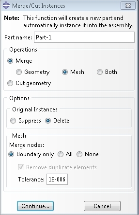
@Dave442, Should I merge nodes for "Boundary only" or "All"?
I have tried both and they remove different numbers of nodes.

PrtScr_capture_qac5jr.jpg
 
if each of your mesh instances lines up perfectly and you have set an appropriate tolerance it shouldn't matter whether you select "boundary" or "all". Ultimately, you should merge out the same number of nodes. The fact that you're merging out different numbers of nodes when you select "boundary" and "all" suggests that something isn't perfectly aligned. This might explain your original problem with the propagation of mesh seeds. When you merge instances you should do it one at a time to start. You can visually inspect what nodes are being merged as they are highlighted during the process. This should allow you to identify your issue pretty quickly.
 
@Dave442, You are right!

I used Tolerance of 1e-6 and got differnt numbers of nodes merged out.
I kept increasing the tolerance and using 1e-4 gave an equal number of merged out nodes for both "Boundary only" and "All".
Using 1e-3 did the same but merged out nodes number increased.
Using 1e-2 gave this warning -

PrtScr_capture_posktt.jpg


So the trick is to keep increasing the tolerance until the warning pops up about tolerance exceeding shortest element edge length, and check if the number of merged out nodes is same for both "Boundary only" and "All".
 
You need to verify that you are only merging coincident nodes. If your individual mesh instances are aligned perfectly, you would not see any difference whether using "all" or "boundary" at tight tolerances - but you do. The fact that you cant do this suggests that something is not aligned perfectly. When you increase the tolerance does the total number of merged nodes increase? If so I'd guess that you're just catching non-coincident nodes in the merge and haven't solved your problem at all.

Increasing the tolerance until the problem goes away isn't "the trick" - it's just reckless.

If you post your original mesh someone can help identify your issue.

 
You can also use the "Mesh gaps/intersections" tool in the Query toolset to check for small gaps and incompatible faces
 
@Dave442, I have done copy-mirror operation in the Part Module to get the full geometry, instead of instancing in Assembly Module. The merged out nodes number is same for maximum tolerance just before shortest element edge length warning pops up.

"Mesh gaps/intersections" tool in the Query toolset gives out element set/numbers, would have been much help if I could see the Nodes.
 
Status
Not open for further replies.

Part and Inventory Search

Sponsor