Continue to Site

Eng-Tips is the largest engineering community on the Internet

Intelligent Work Forums for Engineering Professionals

  • Congratulations Toost on being selected by the Eng-Tips community for having the most helpful posts in the forums last week. Way to Go!

Mesh Gluing 1

Status
Not open for further replies.

MegaStructures

Structural
Sep 26, 2019
376
Hello all,

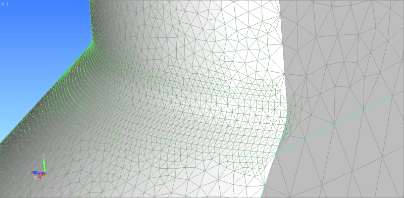
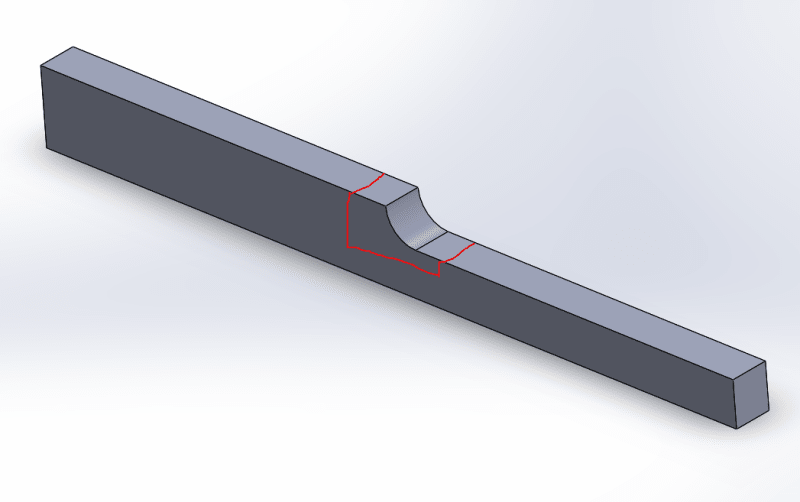
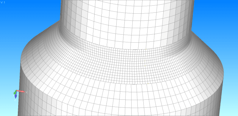
I would like to make sure I am not unintentionally introducing errors into my model by gluing non coincident hex meshes as below. I understand 'gluing' surfaces adds rigid elements to connect the nodes of the touching elements, which is why I have moved my glue point away from my anticipated stress concentration at the radius of the transition. Is there any issue with this setup?

Alternatively I can cut this object in 4 pieces, mesh a surface, and revolve the elements, but that results in over a million elements, where this method results in ~200,000.

Glued_Mesh_k0cqbd.png
 
Replies continue below

Recommended for you

I imagine gluing the surfaces is like our classical assumption "plane surfaces remain plane". Yes, I think this corrupts the FEA, but possibly not so much as to make the results unusable.

I'd use a TET10 mesh, with increased mesh density near the fillet.

another day in paradise, or is paradise one day closer ?
 
Hello!,
Not bad using GLUE surface-to-surface effect with Simcenter Nastran in FEMAP, the only caution is not have very different mesh sizes at the contacting regions: for me a difference of 3 elements to 1 element is correct, more is dangerous.
Glue is a simple and effective method to join meshes which are dissimilar. It correctly transfers displacement and loads resulting in an accurate strain and stress condition at the interface. The grid points on glued edges and surfaces do not need to be coincident. Glue creates stiff springs or a weld like connection to prevent relative motion in all directions.

Also the important question here is to define the GLUE condition effect far away from any stress concentration area or region of interest.

Best regards,
Blas.

~~~~~~~~~~~~~~~~~~~~~~
Blas Molero Hidalgo
Ingeniero Industrial
Director

IBERISA
48004 BILBAO (SPAIN)
WEB: Blog de FEMAP & NX Nastran:
 
rb1957 I used TET10 elements first, but my model is quite large and I had to use an incredible amount of TET10 elements in this solid, which made my model almost unusable.

Blas - I doubt I will have to refine this mesh, since I am seeing such high quality with Jacobians <0.2, but if I did want to test convergence and double the mesh size at the fillet this method would no longer be accurate, because I would be seeing a mesh size 6 times smaller than the coarser mesh of the rest of the part, correct? In your approximation does it appear that my glue location is far enough away from radius of my fillet that is the area of interest?

Do you feel that these glued HEX elements would be more accurate than the model made from TET elements seen below?

(Edit: I thought more about this and these nasty elements likely exist, because I have cut a slice out of the model. Normally there would be a nice smooth mesh around the entire circumference of the surface that would solve this issue)I also have a separate question about TET meshing. Normally I control the size of my TET mesh by using the surface mesh controls in the meshing toolbox. It is not clear what is going on under the surface when editing this way, so I decided to cut a slice out of this solid and edit the surface mesh to see the results. It looks like there is really nasty elements under the surface, any concern that this sort of thing would significantly impact the results of the model?

Tet_Mesh_onnzph.png
 
Hello!,
Of course, when available mesh with CHEXA 8-nodes elements, is far more accurate than CTETRA 10-nodes elements, and the model size is around 10 times smaller, no color!. Your HEX model is correct.

Only in situations where HEX meshing is not possible yo can use either PYRAMID elements for mesh transition from HEX to TETRA (new in FEMAP since last version 2020) or use GLUE surface-to-surface condition. The second method is my preferred one, CPYRAM elements produced by the FEMAP mesher has a bad quality ... not very happy.

Best regards,
Blas.

~~~~~~~~~~~~~~~~~~~~~~
Blas Molero Hidalgo
Ingeniero Industrial
Director

IBERISA
48004 BILBAO (SPAIN)
WEB: Blog de FEMAP & NX Nastran:
 
Blas, thank you for your great advice as always. I will keep my model created with CHEXA elements.

rb1957 - I am not ignoring your opinion that glue may introduce some error if you have some evidence, or explanation to that send it my way, for now it seems that gluing the non-coincident mesh away from the stress concentration is accurate and efficient.

Thanks all for the great help. Love this forum!
 
MegaStructures you can make small test example, like beam with fillet, shown on picture and compare gluemesh vs uniform mesh. There is no magic, you always have some stress discontinuity at the glue interface but fine mesh may reduce discontinuity amplitude and if the glue region is far enough from the region of interest then you can don't care about this discontinuity at all.
%D0%A1%D0%BD%D0%B8%D0%BC%D0%BE%D0%BA_cpruwf.png
 
Status
Not open for further replies.

Part and Inventory Search

Sponsor