Continue to Site

Eng-Tips is the largest engineering community on the Internet

Intelligent Work Forums for Engineering Professionals

  • Congratulations waross on being selected by the Eng-Tips community for having the most helpful posts in the forums last week. Way to Go!

Mesh Interpenetration

Status
Not open for further replies.

chamansrv

Materials
Jul 7, 2015
20
Hi,
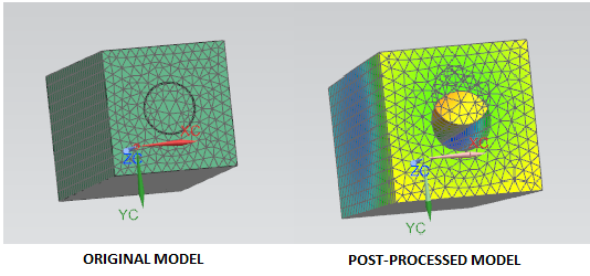
Is there any substitute like embedded elements(ABAQUS) in NX 10.02? I'm having mesh interpenetrations in my results, which I don't want.

Regards
 
Replies continue below

Recommended for you

Hi,

You mean your result shows penetration?

Possible to show some screen capture or share your input file?

Regards,
Tuw
 
Hi Tuw,

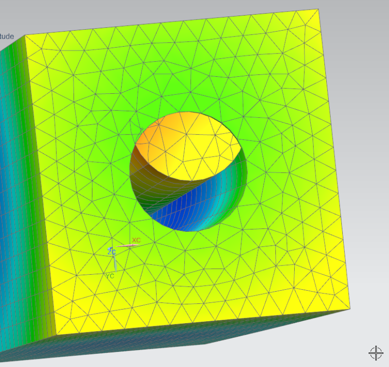
I'm sharing my screen shot.
2015_07_28_11_26_55_NX_10_Advanced_Simulation_Simulation_Cylinder_Beam_fem1_sim1.sim_Modifie_xvpifg.png

ZOOM_rbdysz.png


I hope this is clear. I'm also uploading my input file. Please find it in the attachment.

Best Regards
 
Dear Tuw,

Thanks for the trick.

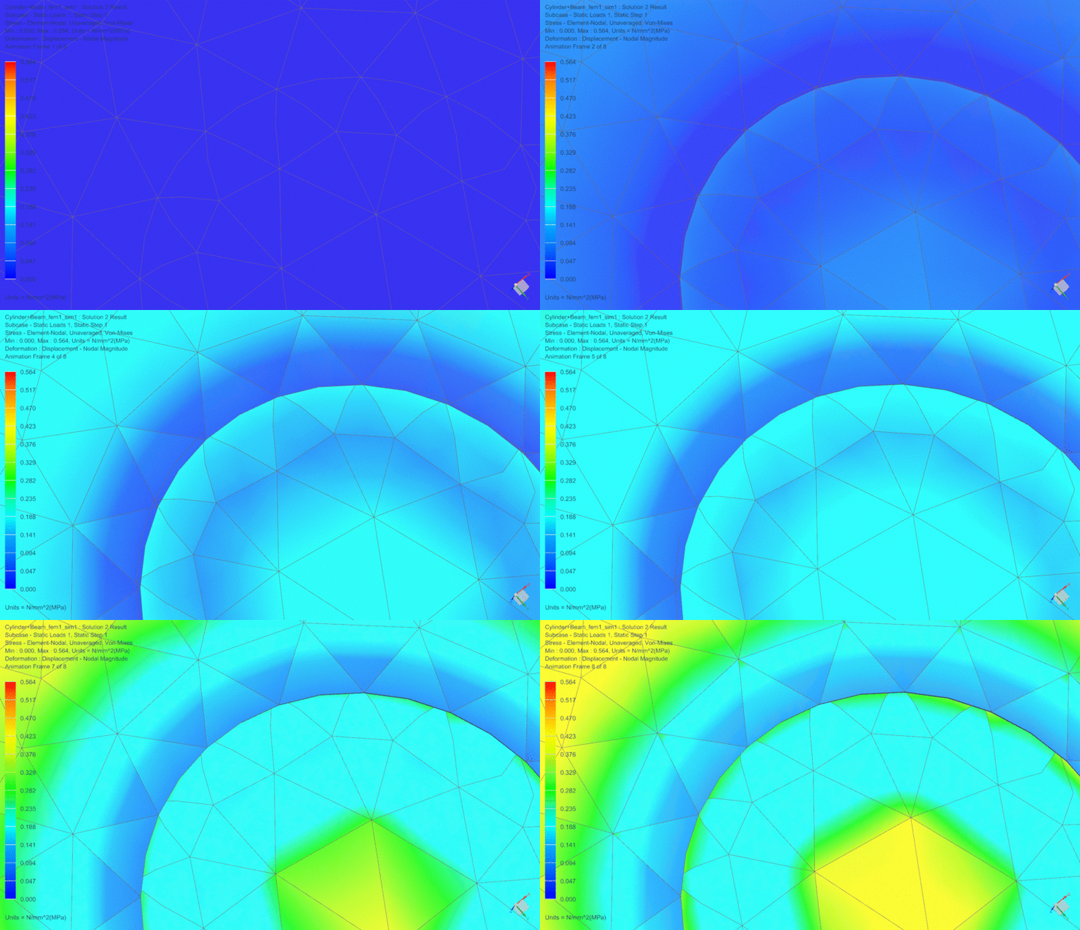
I think it was a bit exaggerated. I changed the post view setting as given in the thread you mentioned, but still, I don't get the deformation. I'm adding a .gif file of my simulation. There you can clearly see the meshes merging into each other.
demo_fha2sd.gif


I hope I'm clear about the problem.

Best Regards
 
Hi Chamansrv,

.f06 file is a diagnostic file. Also I have trouble downloading this file. Maybe you can zip it first before uploading it.

Please provide .dat file which is the input file..

Regards,
Tuw
 
Hello!,
Post your NX FEA model to see what happens clearly, for me it seems that common nodes are not merged between both bodies, then deformation shape is the one you get.

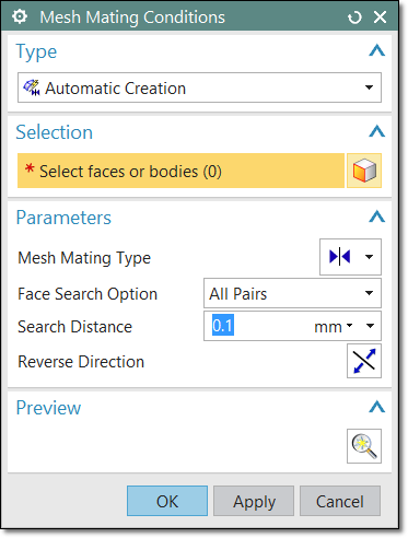
When dealing with assemblies in the FEM environment you need to use command MESH MATING CONDITIONS to connect individual 2D or 3D meshes together at a specified interface. The software ensures that connectivity is maintained at that interface.

MESH-Mating-condition_slnzo9.png


For example, you can use Mesh Mating Condition to:
[ul]
[li]Connect the meshes on similar bodies within an assembly.[/li]
[li]Create identical meshes on two faces to facilitate contact definition.[/li]
[/ul]
You can only use the Mesh Mating Condition command to connect meshes between bodies. You cannot use Mesh Mating Condition to connect mesh mating conditions within a single body. Depending on the option you select from the Mesh Mating Type list in the Mesh Mating Conditions dialog box, you can connect:
[ul]
[li]A solid body to another solid body.[/li]
[li]A sheet body to another sheet body.[/li]
[li]A sheet body to a solid body.[/li]
[li]A surface wrap body to a surface wrap body.[/li]
[/ul]
With a Glue Coincident condition, the software makes both the geometry and the meshes match between the source and target faces.
[ul]
[li]If the source and target faces are geometrically identical, the software merges the two faces to create a single face that is shared by the two bodies. This shared face is sometimes referred to as a non-manifold geometry condition. If the source and target faces overlap each other and are geometrically identical, the software merges the faces in the overlapping region and creates a single, shared face.[/li]
[li]When you mesh the shared face, the software only generates the nodes on the source face. The nodes on the shared face, including the nodes on the edges of the shared face, belong to the bodies associated with the source and target faces.[/li]
[li]If the two faces are not geometrically identical, the software imprints the common area between the faces on both of the faces. The software then uses that common area as an identical geometric pair which it can process further.
[/li]
[/ul]
Best regards,
Blas.


~~~~~~~~~~~~~~~~~~~~~~
Blas Molero Hidalgo
Ingeniero Industrial
Director

IBERISA
48004 BILBAO (SPAIN)
WEB: Blog de FEMAP & NX Nastran:
 
Status
Not open for further replies.

Part and Inventory Search

Sponsor