Hi,
Looking for some advice or clarification that I understand how Mechanica works with respect to meshing.I have created a simple test part shown below and gone through many of the mesh settings to understand the influence they have.
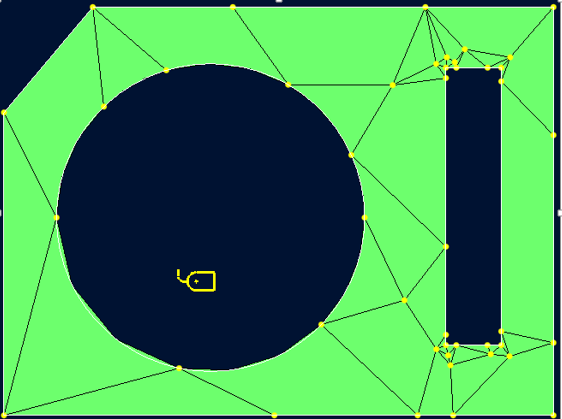
My question is, is the default mesh shown below on the left sufficient?
I understand Mechanica uses the p-element method which means a mesh can be coarse and results are obtained by increasing the order of equations until convergence is achieved, so I think this mesh is OK?
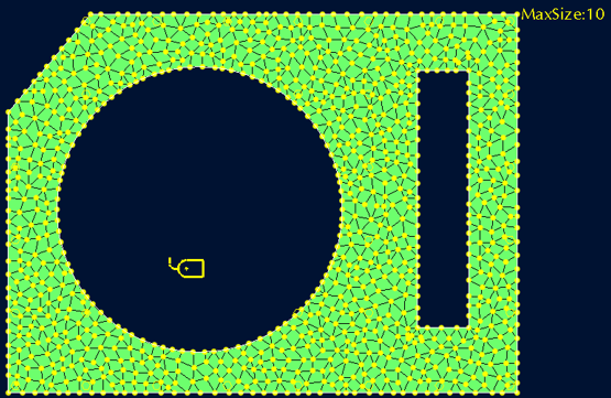
I am working with some people who used to different programs and they desire that I create a more uniform mesh - kind of like I have created in the bottom right picture by limiting the max element size. But is this approach good practice with mechanica? I guess it would significantly increase the analysis time?
If anyone can give some advice and let me know if I am understanding this correctly it would be much appreciated.
Update:
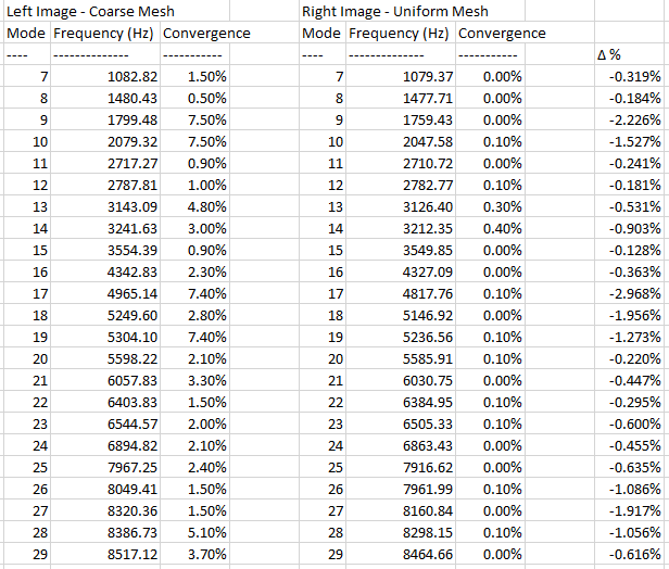
I performed an unconstrained modal analysis on both and compared the results - see bottom pic. I see there is a lower convergence % for the more uniform mesh - is this more desirable?
Thanks
Looking for some advice or clarification that I understand how Mechanica works with respect to meshing.I have created a simple test part shown below and gone through many of the mesh settings to understand the influence they have.
My question is, is the default mesh shown below on the left sufficient?
I understand Mechanica uses the p-element method which means a mesh can be coarse and results are obtained by increasing the order of equations until convergence is achieved, so I think this mesh is OK?
I am working with some people who used to different programs and they desire that I create a more uniform mesh - kind of like I have created in the bottom right picture by limiting the max element size. But is this approach good practice with mechanica? I guess it would significantly increase the analysis time?
If anyone can give some advice and let me know if I am understanding this correctly it would be much appreciated.
Update:
I performed an unconstrained modal analysis on both and compared the results - see bottom pic. I see there is a lower convergence % for the more uniform mesh - is this more desirable?
Thanks