Eng-Tips is the largest engineering community on the Internet

Intelligent Work Forums for Engineering Professionals

Meter shows current values during CT secondary injection but zero after energization 2

Status
Not open for further replies.

chao_david

Electrical
Oct 25, 2017
15
0
0
PH
Here's the SLD for reference:
SLD_qmmwhz.png


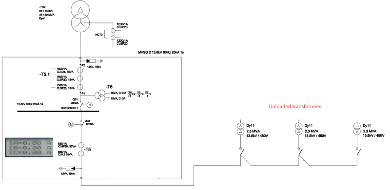
Before the three pad-mounted transformers were energized, contractor performed secondary injection on T5 CT to check accuracy of meters. All results are good.

After energizing the high side of the transformers, there is no reading on the meter. I was expecting some no-load current reading but all phases are zero Amps.

1. I've checked the LBS on the transformer and nothing is isolated
2. Fuses are intact
3. Ratio settings are correct

What else could it be?
 
Replies continue below

Recommended for you

I don't expect the no-load current of all the three pad mounted transformers put together, will be greater than 20A.
The CT primary rating is 630A. I don't think the CT can transform such low current and also don't think the meter can read (whatever the CT transforms) properly. The CT and meter errors are supposed to be large when the current is below 25% of the rated current.

R Raghunath
 
Part of the accuracy information of a CT is presented in the form of an excitation curve.
Example
9-ct-diagram-excitation-curves_yhomfv.jpg


Are the current transformers metering grade CT's or protection grade.
Metering grade might show accurate current, but it might be to low for your meter to indicate. For protection grade trying to measure a small current that falls inside the error band is suspect.

See this link for details regarding the differences, and why the two types exist and why they are not interchangeable.

 
Those three pad mounted transformers showed in SLD will draw around 0.9A in total(Considering 0.3% no load current) during no load condition. So, T5 CT secondary will give 0.9*5/630=6.9mA as output. Each meter and protective relays has a minimum resolution. That's why you are not seeing any current during energizing. It's quite normal.
But If meters do not show any current during loading condition, then you need to check for bad connection of CTs or meters.
Thank you.
 
Depending on what the "meter" is, it might have a dead band around zero and will just show zero until you get outside that dead band.

When one this sentence into the German to translate wanted, would one the fact exploit, that the word order and the punctuation already with the German conventions agree.

-- Douglas Hofstadter, Jan 1982
 
I have the following opinion, for your consideration.
1. T-5 has 2 cores, one of them is 630/1A , Cl 0.2 15VA. This is the metering/measuring CT. Ensure that the ampere meter is connected to this CT.
2. Assuming that 3 secondary open-circuit trafo with total no-load current of 0.9A, the CT output current = 0.9A/630A x 1A =1.42mA, or 0.142% of 630A. With is extremely low current, even a Cl 0.2 CT is NOT expected to perform within the tolerance.
3. Info: a) usual measuring range 5-120%.
b) see IEC 660044-1 for further details.
4. Check when any one of the trafo is loaded. If still reads 0A, a thorough check on a) open circuit/high contact resistance along the line b) shorting links not removed on the terminal blocks after the injection tests; c) the meter is open circuit/faulty.
Che Kuan Yau (Singapore)
 
For most testing we do, we would expect 0.5 amps secondary for an accurate test.
Besides that, CT's are transformers, and have a minimum voltage to fully excite the core.
 
Thanks everyone. It seems that the no-load current is too low since we've tried to check the reading the moment the transformers were energized. We've seen around 200 Amps for the inrush current then back to zero once stabilized.


It is a bit unusual since we have several BESS projects and this is the first time that we had "zero" no-load current. All equipment specs are identical for each project, even the distance of the transformers to the MVSG.

 
What kind of relay are you using? Expanding on DavidBeach's comment, even identical relay models from the same vendor have different deadbanding characteristics depending on the firmware version. In some relay models the default setting is the deadbanded version, but the raw version is also available. This can be headache for locations where we serve industrial customers that have very low loads on nights/weekends.
 
Expanding further again on relays, some have true RMS readings but also have raw / Fourier filtered measurements.
The true RMS needs a bit more current to display anything compared to the "raw" measurements.
Also in addition to different Zero deadbands in different devices and firmware version - ZeroDB can sometimes a setting in the device - worth checking.
If you have the equipment, I'd recommend using a sensitive tong ammeter to measure the current going in to the device from the CT secondary.
Verify what is being measured on the tong ammeter is what you would expect. If it isn't, then there might be a wiring problem.
If that all looks OK, then inject that measured value into a spare device with the same settings and see how it displays.
if it is showing zero, raise the current until it displays, then look in the settings/manuals etc for a match.
Checks of measurements without load can often produce misleading results.
 
What can be lots of fun is when the natural imbalance means that one or two phases read non-zero while the other two or one read zero. I think that actually results in more questions than having all three show up as zero.

When one this sentence into the German to translate wanted, would one the fact exploit, that the word order and the punctuation already with the German conventions agree.

-- Douglas Hofstadter, Jan 1982
 
Or having a switch to switch what phase the amp meter reads. Then asking why the three phases read differently? Then asking why the ground relay is not picking up?
Then comes the long explanation that not all unbalance is zero sequence.
 
I’d double check for shorting screws and wiring errors and lifted wires. If you have a technician who has the right equipment they can plug in to test switches (if provided) and measure current directly. You also might be able to use a clamp on milliamp meter.

Casey
 
Status
Not open for further replies.
Back
Top