Continue to Site

Eng-Tips is the largest engineering community on the Internet

Intelligent Work Forums for Engineering Professionals

  • Congratulations pierreick on being selected by the Eng-Tips community for having the most helpful posts in the forums last week. Way to Go!

Micropile Connection to 800mm thk Raft

Status
Not open for further replies.

EireChch

Geotechnical
Jul 25, 2012
1,332
Hi all,

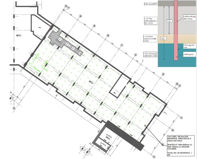
I am working on a project that requires underpinning of a large structure which has settled excessively. We are asked to evaluate the use of micropiles to support the 800mmthk raft. Approx 1000mm of earth fill and a 200mm thk floating slab sit above the raft.

The 168mm dia micropile, and 250mm drill hole are to extend 8m through bad fill and into Siltstone/Limestone. Total length is 13m.

The connection through the raft is the tricky part. I have proposed 3 options and interested to hear your thoughts. It would be great if someone has undertaken Option 3 before with success!!

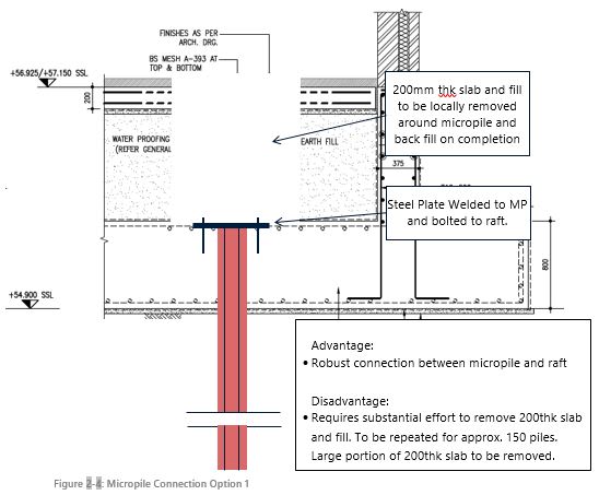
I believe there are three options, Option 1 which involves breaking out the 200thk slab and earth fill and bolting the micropile to the slab. This requires a considerable amount of work but provides a solid connection.

Capture_cz385b.jpg


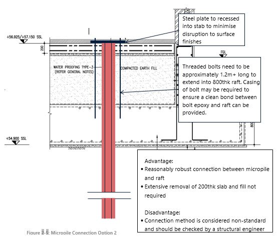
Option 2 is similar to option 1, only that the plate is located on top of the 200mm thk slab. In theory it should be as sound a connection as option 1 but obviously less practical with 1.2m+ long bolts.

Capture_s1oldo.jpg


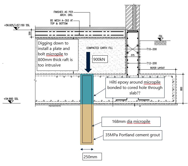
Option 3 is likely the easiest however least robust. We have a 250mm core through the slab, this will leave a smooth hole that isnt great for bonding too! I am aware that there are roughing tools out there but maybe not 250mm in dia. Also, do you think its possible for a epoxy/concrete bond to take 900kN...

Capture_gupbzp.jpg


I have been in touch with HILTI and they havent helped much.

We are providing several options and it looks like LMG columns will be the preferential one!
 
Replies continue below

Recommended for you

Is your load a factored or unfactored load? 900kN ( 202 kips) is a big load per each of your 3 micropile connection options. Consider more micropiles (more connections) with lower design loads.

 
Is the raft capable of being supported only at the perimeter? What about a combination of perimeter minipiles and pressure grouting in the interior of the raft? Obviously, perimeter attachment is easier.

 
Thanks PEinc and Ron.

Yea 900kN is actually the structural capacity if the uncased bonded length in rock.

The max column load is approx 6000kN. We are proposing to install 8 micro piles beneath the column at a 1m spacing. The load per micro pile is approx 900kN (which included weight of raft and fill etc). Columns are spaced on a 5 x 7m grid approx.

We can add more micropiles to bring the load down but we still have the connection issues.

Do you think is possible to connect the raft with just an epoxy. Relying on bond resistance between the 800mm length. That connection is by far the easiest to construct.

Ron, the plan dimensions are 51m x 22m so the raft won’t span.

The issues above are generally forcing us to go down the LMG column route. I believe the is the best option as it provides a structural support as well as increasing the density of the fill!
 
EireChch - I sent your note to an 82 year old French mate of mine who has vast experience - up there with my mentor Fred Matich and Oldestguy (Cliff Lawson). He was full of questions . . .

"Question: Philippe – have a look at this thread and give me your thoughts. It looks to be right up your alley! BigH

Answer: This scheme leads to comments that I am interested to share with you and your mate. However, I need more information, should they be available.

It derives from the attached sketches that the raft is the deep foundation of a covered structure. What is the purpose of the structure/building?

• Is a sketch of the overall size of the raft available together with the round figures of the length and width?

• Tentative lay out of the micro piles or typical spacings.

• Is the 200mm surface slab transmitting vibrations to the 1000mm earthfill due to heavy industrial activities on top of the 200mm floating slab?

What is the Load Design of this slab?

• What is the kind of backfill material in between the raft and top slab?

• To confirm that the tentative thickness of the “bad fill” material below the bottom face of the raft and the top of the Siltstone/Limestone horizon is in order of 8 meters and to confirm that the micropiles will penetrate in the range of 5 meters in the Siltstone/Limestone horizon.

• Is information available upon the components and grading of the “bad fill”?

• What LMG stands for?

• Is there any underground leakages/seepages/water table?

• Is the site subject to earthquakes?"

I guess you could take some of these are additioal points to consider.
 
Thanks BigH, responses below.

Answer: This scheme leads to comments that I am interested to share with you and your mate. However, I need more information, should they be available.

It derives from the attached sketches that the raft is the deep foundation of a covered structure. What is the purpose of the structure/building? The building is a 6 storey hotel

• Is a sketch of the overall size of the raft available together with the round figures of the length and width? I wanted to link the layout but I dont know how to!, Draft layout shown below. MPs spaced at approx 1800mm to 2000mm, reduced to 1000mm beneath columns. Raft is 51m x 22m approx.
Capture_q8euuq.jpg


• Tentative lay out of the micro piles or typical spacings. As above

What is the Load Design of this slab? I dont know the load case that is critical, however column loads range from 3-6000kN, the applied pressure from the raft ranges from 60-140kPa. Average pressure would be approx 100kPa.

• What is the kind of backfill material in between the raft and top slab? Drawings show it as "Earth Fill", we imagine this is a poorly graded sand. We have considered settlement of this fill as a source of problem, however we have settlement markers on the underlying raft which show fill below the raft as a problem.

• To confirm that the tentative thickness of the “bad fill” material below the bottom face of the raft and the top of the Siltstone/Limestone horizon is in order of 8 meters and to confirm that the micropiles will penetrate in the range of 5 meters in the Siltstone/Limestone horizon. The maximum MP length will be 13m, which includes 5m into Siltstone. On the west portion of the building, rock is shallower so MP length may only be in the order of 7m. We are still at concept stage so are indicating 13m long MPs. We have included recommendations that this can be optimized during detailed design stage.

• Is information available upon the components and grading of the “bad fill”? Grading curves show it as a poorly graded SAND, sandy GRAVEL, and GRAVEL. All the historical earthworks compaction test show that it has met 98% MDD, etc. However, we have SPTs which show N values of 1-4 through the supposedly engineered fill.

• What LMG stands for? Low Mobility Grout, a type of compaction grouting. Typically used for underpinning.

• Is there any underground leakages/seepages/water table? No leaks identified, water table is at 20m+

• Is the site subject to earthquakes?" Yes, site is in a moderate seismic zone.

I guess you could take some of these are additioal points to consider.
 
Grants, a comment from the structural engineer is that “ that many holes will compromise the structural integrity of the slab”?

Thoughts?
 
Colleagues: The attached is from a mate of mine - 82 years old so not yet to Oldest Guy. He is a very thorough engineer. EireChch - hope this helps and is not too late. He had French taxes to get out of the way. [Cheers]
 
 https://files.engineering.com/getfile.aspx?folder=a68dd33d-f4e2-40b1-b96f-e898354bfc55&file=Responce_to_EireChch_Post_of_Mar_31_2021.docx
BigH - thank you for this. Much appreciated. I will draft a reply soon, just havent got around to it yet!
 
Status
Not open for further replies.

Part and Inventory Search

Sponsor