Continue to Site

Eng-Tips is the largest engineering community on the Internet

Intelligent Work Forums for Engineering Professionals

  • Congratulations SSS148 on being selected by the Eng-Tips community for having the most helpful posts in the forums last week. Way to Go!

Minimum aggregate size to achieve assumed shear plane capacity

Status
Not open for further replies.

bugbus

Structural
Aug 14, 2018
533
With regard to the strength of shear planes at cold joints / construction joints, is there a minimum aggregate size required to ensure that the aggregate interlock component of the shear capacity is achieved?

The various codes normally state a minimum roughness that has to be achieved, but not a minimum aggregate size:

AASHTO & ACI - minimum roughness 1/4" (6.35 mm)

AS3600/5100.5 - interface must be 'deliberately roughened' - requirements by various authorities include NSW RMS (3 mm minimum roughness). Minimum aggregate size covered by the codes is implied to be 10 mm but not stated explicitly (as far as I can tell).

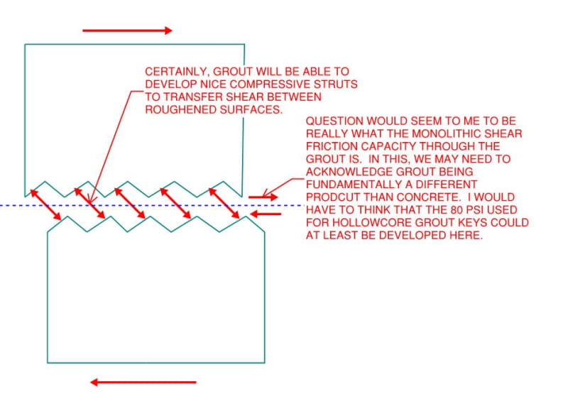
I have a situation where two precast elements are to be joined. The faces of the precast elements will be roughened to the minimum amplitude, the gap (50 mm wide) between them grouted with high strength cementitious grout, and after the grout achieves a certain strength the elements are post-tensioned together with several high tensile bars. The interface is required to transmit a relatively large shear force and has been designed based on the Australian code, assuming a 'deliberately roughened surface'.

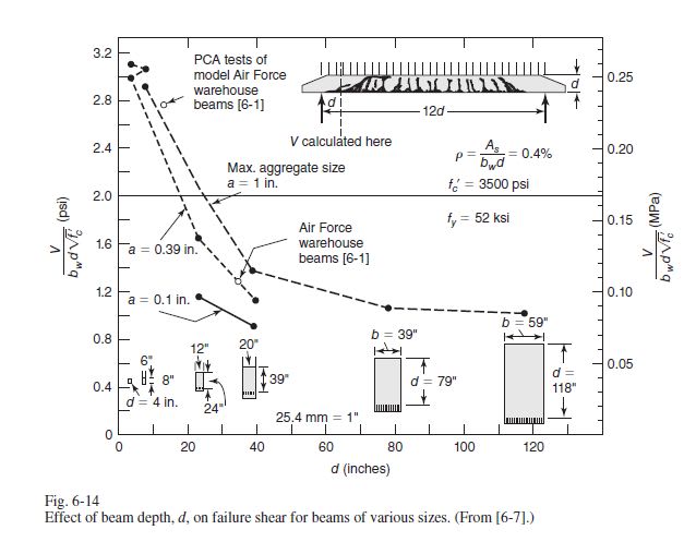
I am wondering whether the grout in the gap ought to have a coarse aggregate added, and what its minimum size should be. My feeling is that, yes, this requires a coarse aggregate since the potential shear plane could form right through the middle of the grout layer. The grout supplier states that a 10 mm aggregate can be included in the mix. But would a smaller aggregate be OK? 3 or 6 mm?
 
Replies continue below

Recommended for you

I suppose this (or shear friction in general) would ultimately be influenced by the strain in the shear friction reinforcing? Interesting question. I don't have any books handy, so I don't know if they (ACI) address this in the code commentary. I'd assume a fine aggregate grout wouldn't provide much strength in the way of aggregate interlock either way though. My mind says...crumbling sand paste. If the gap were 1/4" (~6mm) , I might give it more consideration as the roughened surface may be able to directly transfer this shear by way of bearing (think: strut - i'm no expert in that field though - paging Koot, et. al.) to the other roughened surface. 2" gap...not so much.

Any other takers?
 
The title of the thread (Minimum aggregate size to achieve assumed shear plane capacity ). But probably better to change to (Maximum aggregate size allowable to achieve minimum shear plane capacity )


The following is excerpt from Reinforced Concrete
Mechanics and Design (by James Wight )

Coarse Aggregate Size. As the size (diameter) of the coarse aggregate increases, the roughness of the crack surfaces increases, allowing higher shear stresses to be transferred across the cracks. As shown in Fig. 6-14, a beam with 1-in. coarse aggregate and 40-in.effective depth failed at about 150 percent of the failure load of a beam with d = 40 in. and 0.1-in. maximum aggregate size. In high-strength concrete beams and some lightweight concrete beams, the cracks penetrate pieces of the aggregate rather than going around them, resulting in a smoother crack surface. This decrease in the shear transferred by aggregate interlock along the cracks reduces Vc.


besm_depth_agg_size_vs_shear_failure_jvcbuz.jpg


ACI 318 -14 26.4.2 Concrete mixture requirements ,26.4.2.1 Design information:
(4) Nominal maximum size of coarse aggregate not to
exceed the least of (i), (ii), and (iii):
(i) one-fifth the narrowest dimension between sides
of forms
(ii) one-third the depth of slabs
(iii) three-fourths the minimum specified clear
spacing between individual reinforcing bars or wires,
bundles of bars, prestressed reinforcement, individual
tendons, bundled tendons, or ducts


I will suggest 8 mm max. aggregate size for 50 mm wide gap.
 
dold said:
...paging Koot, et. al.

1) I can't resist a good summons...

2) I, also, am no expert in this area.

3) I think that it's important to note that:

a) Shear friction and classic, diagonal tension, beam shear are different but related things and;

b) I think that this is shear friction, not diagonal tension.

As such, I don't feel that all things diagonal tension shear necessarily apply here.

4) The world of precast is exceptionally pragmatic, as befits their role in the structure-verse. This may ultimately have to come down to a solution that is precast specific rather than strictly ACI compliant.

5) Anecdotally, grout has been used in a shear friction-ish manner in hollow core plank diaphragms for a long time: Link. And that, without any explicit shear friction reinforcing. Perhaps the relatively low, 80 PSI limit that they place on that capacity would be a good fit for this situation.

6) I too harbor a visceral concern over cyclic integrity where seismic would be an issue. That said, there is still the hollow core diaphragm example which has been tested cyclically: Link.

7) Personally, I would seek to use small aggregate for the grout rather than large. As someone who's seen this get done in the field, I'm a lot more concerned with a quality install than I am whether or not the aggregate maxes out interlock potential.

8) Whenever this comes up, there is always the question of whether or not the grout, even expansive grout, can be relied upon to not shrink up long term and compromise shear capacity. Certainly the post tensioning of the proposed system makes me feel a lot better about this. Larger aggregate does tend to reduce shrinkage, all else being equal.

9) I see the mechanics of the situation as shown below.

C01_tpoeoi.jpg
 
@ HTURHKAK - Thanks for your response. I take your point but maybe I wasn't being very clear. What I really was looking for was the minimum, maximum-aggregate-size. Obviously the absolute minimum aggregate size would be very fine in this case. The maximum aggregate size in the precast elements is 20 mm, and all the normal shear strength checks (let's call it diagonal shear) in these elements is easily satisfied based on the Australian Standard, which uses MCFT.

@ KootK - Thanks to you, too. Seismic is not such a concern in this case, without getting into too many specifics about this particular structure. I agree with your point about quality, I think this is really a question for the grout supplier (big, international name, which I won't mention). I have reached out to them for advice and am waiting to hear back, but I will share their recommendations when I get them. Regarding shrinkage, I agree with that concern but I am confident that the level of prestress and the length of the elements compared to the 50 mm gap is enough to avoid any crack opening up.

As KootK points out, I think this really comes down to whether a failure plane could form through the middle of the grout. If an aggregate is added to it, however, I don't really see how it would act much differently to concrete. I have no doubt that grout without aggregate, or with very fine aggregate, would be a different story.


I'm so glad I read this. Not a question I've really considered before. I usually specify #57 stone for slabs and foundations and #89 stone for tie beams. #89 stone has a maximum aggregate size of 3/8 In (.375 in). According to the chart above the decrease in shear strength is almost 25% for 24 inch deep beam (approximate). That is pretty signficant. The good news is that to ignore reinforcment requirements 1/2 phi Vc must be greater than Vu. So the 1/2 factor has this fluctuation covered pretty good if you stay between 3/8" of an inch and 1". #89 stone works well for pump mixes so there really shouldn't be a need in normal circumstances to go below this. Besides once you add shear stirrups (cause most beams require reinforcement) I think this issue plays an even smaller factor in the beams overall shear factor of safety. This is for beams though not shear friction.

Regarding the issue of shear friction. Regarding #5 of KootK's post it's been a long long time since I've done a hollowcore plank job. But I do remember finding equations and typical details with hook bars used across the shear friction joints of hollowcore diaprhagms. Basically using hooked rebar from the wall into the concrete topping. At least that is how I've always done it. I've seen drawings in the past without anything. I personally don't think this is correct especially thought when also considering out of plane shear loads. But that is just my two cents. I'm pretty conservative.

Regarding using a grouted shear key I honestly don't know if this works or is even allowed. I've only used shear keys or shear friction in very limited capacities. When I look at the diagram KootK posted above to me this looks almost like a double shear key with each interface independent of the other. One way to look at it would be to just look at one side of the key and assume the grout is an independent component with the opposite face supported. (so three components total) If there is a compression force across the joint it is hard to imagine what the failure mode crack would be. It would be so deep versus its span there is no room for a diagonal crack like you would see in a diagonal beam tension failure. The entire joint would be in compression in direction of the shear. And a perfectly straight crack would be difficult to form if there is compression or post tension compression across the joint clamping the two members together. You could do some kind bearing failure check in addition to the traditional shear friction equations.

However, if you do not have a compression force across the joint or its not a constant compression force, than you could develop tension due to the eccentric moment caused by (Shear Force x Joint Width). This might make the joist unstable and|or reduce the depth of your shear friction bearing area.

I don't know what type of loads you are attempting to transfer but boy be careful. That Pedestrian Bridge failure at FIU was basically a shear friction failure. Just be really careful. Oh and take whatever I've said here with a grain of salt I'm really out of my area on this one.

If at the end of the day your aren't comfortable you might be able to transfer the shear via stainless steel embeds or perhaps even add some post installed and epoxied rebar across the joist.

one more idea to consider. I know if the US where we use the ACI code we have different equations for calculating shear capacity of reinforced concrete and plain concrete. Looking at the grouted portion of the joist as unreinforced you might need to apply different shear equations for Vc using the plain concrete section of the Austrilian code if there is one.

John Southard, M.S., P.E.
 
Status
Not open for further replies.

Part and Inventory Search

Sponsor