BridgeSmith
Structural
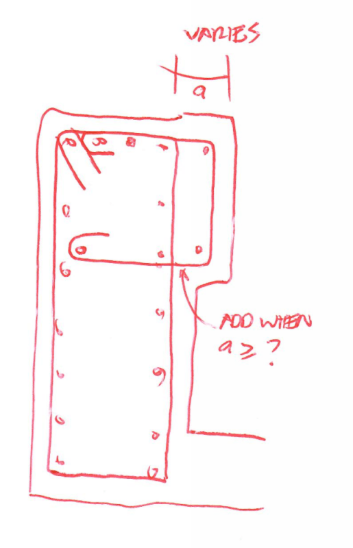
We have a concrete parapet detail with a blockout where the detailing of the rebar would be greatly simplified if we could do a double bend to create a small offset or jog in the bars.
[URL unfurl="true"]https://res.cloudinary.com/engineering-com/image/upload/v1561038826/tips/parapet_reinforcing_nvypct.pdf[/url]
Is there is a limit on how small an offset can be made when bending the bars? We've always detailed ours with 2 times the bend radius as a minimum, but I'm wondering if we need to.