Eng-Tips is the largest engineering community on the Internet

Intelligent Work Forums for Engineering Professionals

  • Congratulations waross on being selected by the Tek-Tips community for having the most helpful posts in the forums last week. Way to Go!

Minimum Material Thickness for a Tapped Hole. 2

Status
Not open for further replies.

dik

Structural
Apr 13, 2001
25,565
0
36
CA
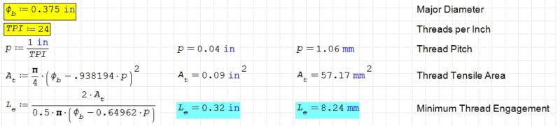
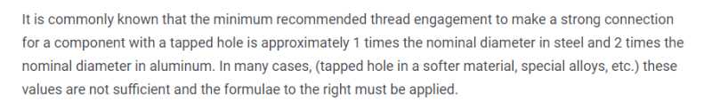
I have a 3/8"-24 dia A307 Grade B fastener going into an HSS 6x6x0.188 column. The client wants to drill and tap the column (doesn't want to use TEKS fasteners which I spec'd). The load is less than 15% of the A307 fastener. Min ISO engagement is 5/16"

Is there a minimum wall thickness that I can use? Is calculating the capacity with a good comfy factor adequate? and ignore the engagement length? I don't have a problem doing this unless there is a real contraindication... and just glue it in place with Loktite Red...

Thanks, Dik

-----*****-----
So strange to see the singularity approaching while the entire planet is rapidly turning into a hellscape. -John Coates

-Dik
 
Replies continue below

Recommended for you

Typical full strength engagement is 3-4 full threads, so 4/24ths of an inch (.170) which is marginal. I'm sure the ISO minimum is for factor of safety. Beyond 3-4 threads there isn't enough elastic deformation to transfer load. First full thread sees almost 50% of the load. You are more likely to see problems from installers giving it the extra oomph they think it needs or being too aggressive with cleaning up the hole with a csink after tapping.
 
Thanks 3DD... Pretty much what I was thinking that 3/16" nearly gives me 4 threads... which not happy about, but think will work... Rather than overtightening, I was thinking of 'glue'. Load is only a few hundred pounds...

Client want to drill and tap... else I'd use TEKS...

-----*****-----
So strange to see the singularity approaching while the entire planet is rapidly turning into a hellscape. -John Coates

-Dik
 
Client driven... not my choice.

-----*****-----
So strange to see the singularity approaching while the entire planet is rapidly turning into a hellscape. -John Coates

-Dik
 
There are formed threads (not cut) where metal is displaced to the backside to add reinforcement.
The brand name for these slips my mind right now.
Some of these systems use a forming die to create a 'lip' for the hole and then use a forming die (not a cutting tap).

= = = = = = = = = = = = = = = = = = = =
P.E. Metallurgy, consulting work welcomed
 
Thanks Ed... that's not the case here... the HSS column will be drilled and tapped. I just realised, the load is 1/2... even better, there are two tapped bolts.

-----*****-----
So strange to see the singularity approaching while the entire planet is rapidly turning into a hellscape. -John Coates

-Dik
 
I had no concern about the load... it's just knowing why it works... I'm kinda quirky when it come do doing things... even wrote up an SMath program for it. A little overkill, but can use it for more interesting stuff in future. I write the programs on my own time... For small loads, I like to see a minimum of 4 thread engagements... but just wondered if there was something that I was missing and that there was a 'defined' minimum thickness... I'd have pointed that out to the client... just don't like the connection, I'm happier with TEKS, which I know works... gluing them in with Loctite Red, to boot since I don't want to overtighten and strip the threads and I don't want the connection to loosen... my only concern.

-----*****-----
So strange to see the singularity approaching while the entire planet is rapidly turning into a hellscape. -John Coates

-Dik
 
Could, but the client wants to drill and tap... TEKS are an obvious solution... but not for this client... I don't know the reason...

I should have added that the STI is a great outfit... been a member for a few years, now...

-----*****-----
So strange to see the singularity approaching while the entire planet is rapidly turning into a hellscape. -John Coates

-Dik
 

pretty close...

Clipboard01_pxachm.jpg


-----*****-----
So strange to see the singularity approaching while the entire planet is rapidly turning into a hellscape. -John Coates

-Dik
 
When investigating thread axial load distribution, as previously mentioned, the 1st thread will see the highest load, and the subsequent threads will see an exponentially decaying load. This is seen in typical preloaded thread joints. On a point of interest, if you are wanting to see what the minimum wall thickness can be, the act of reducing the number of threads to only a few (noting 1st and last are not fully formed), will tend to reduce the difference in the load distribution.
 
Just for interest, if your applied load is tending to pull the bolt out of the threaded hole, the load transfer over the threads will be different to that seen under preload conditions. Under a pullout load, the 1st and last threads will peak.
 

Is there a means of calculating that? I did some quick calcs and with the thickness being less than the minimum thread engagement, I was looking at about 20% of the capacity, and the actual load was a lot less.

-----*****-----
So strange to see the singularity approaching while the entire planet is rapidly turning into a hellscape. -John Coates

-Dik
 
The attachment shows two thread axial load distributions, under preload conditions. One is for 16 threads, showing the typically seen distribution. The second is for 5 threads, showing a lesser variation in the distribution difference. Under a pull-out load, the distribution will be different to that seen under preload. The means of calculating the distribution is quite lengthy, and involves calculating thread shear and bending stiffnesses, and bolt / nut axial and shear stiffnesses. A single shear compatible deformation equation is used for each thread, in conjunction with a known force condition (sum equal to preload), giving the required number of equations for the unknown number of thread load transfer forces to be solved. An alternative method, which still requires all the stiffnesses to be calculated, is to use the shear-lag method. A good reference is The Sopwith (1948) theory.
 
 https://files.engineering.com/getfile.aspx?folder=3a6ed719-0149-4ddc-b4aa-b343c2891a2e&file=Preload_Distributions.pdf
Thanks... I thought it would be pretty complicated.

-----*****-----
So strange to see the singularity approaching while the entire planet is rapidly turning into a hellscape. -John Coates

-Dik
 
Status
Not open for further replies.
Back
Top