Eng-Tips is the largest engineering community on the Internet

Intelligent Work Forums for Engineering Professionals

MMB datum feature simulators used in a restrained condition?

Status
Not open for further replies.

Burunduk

Mechanical
May 2, 2019
2,335
0
0
IL
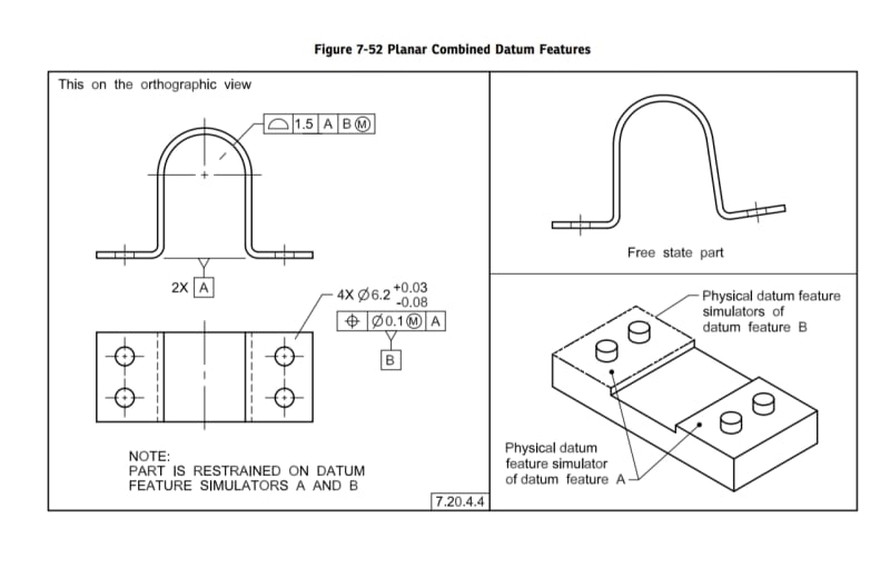
According to sub-paragraph 7.20.4.4 in ASME Y14.5-2018, datum features of size referenced at MMB can participate in restraining the part (producing a restrained condition). The sub-paragraph refers to figure 7-52, which doesn't include a detailed restraint requirements note (a detailed note is available in figures such as 7-27 and includes mounting instructions with fasteners and torque data).
Does anyone have an idea, or can provide an example, of how the four pins used as datum feature simulators of datum feature B in figure 7-52 can be used to apply forces on the part?

Y14.5-2018 7.20.4.4 said:
It may be necessary to use multiple features of size to establish a datum reference frame when a restrained requirement is invoked. For the datum features to comply with the physical datum feature simulators, forces may be applied in accordance with the specified restraint requirement to flex or deform the part. See Figure 7-52.
NOTE: The position tolerance shown in Figure 7-52 for datum feature B (pattern of four holes) is not used to determine the free state location of the holes. It is used to establish the MMB simulators that are to restrain the part to simulate the installed condition


Screenshot_20230315_193306_Drive_kfniuv.jpg
 
Replies continue below

Recommended for you

Simply holding the part tabs flat may not align the pins with the holes and vice versa. It may be the the pins will ride against the closest tangencies of the holes with the pins or the farthest tangencies.

I have encountered a number of actual parts that behave just like this - squeeze the part to allow the screws to be installed and then tighten them to hold the tabs flat.
 
3DDave,
So if the part is deformed enough it may be necessary to force it to fit the MMB simulator pins and that way the pins take part in restraining the part. That makes sense if the part is indeed very deformed, but if the deformation is more moderate and there is sufficient clearance between the holes produced within their size tolerance and the MMB simulators, there might not be any restraint acting through the pins, right?
So the restraint note on both A and B is a requirement on the drawing, but it looks like it will not always be met (for B), and not always necessary either - it could be applicable or inapplicable (for B) per the actual produced part geometry, isn't it?

Would you say that a restraint applied by MMB simulators also makes sense in the upper segment of the control of datum feature E in figure 7-51 (see below)?
The secondary hole and the tertiary slot are used to restrain the part, while the primary datum target planar areas are referenced at free state. In addition to the "deformation not guaranteed" issue from the previous case, I would say that with that part geometry, it looks like it would be difficult to squeeze or stretch or twist the part by force against the MMB pin and tab that will be used as the simulators for the secondary and tertiary B@M and C@M, especially without applying any force against the primary A-D simulators. Would you agree?

Screenshot_20230316_125631_Drive_ns8buo.jpg
 
It's possible the part is perfectly formed and the flanges are perfectly co-planar and there is no need for any restraint.

I think that should be a note - "perform an FEA on the actual geometry of the part and see if any force is necessary and only if force is necessary should force be used."

I expect that would be a way to accept more parts and therefore the hour delay to record and enter the data and then run the FEA for each part would be time well spent. And it would meet your need for precision beyond what is required to understand, manufacture, and inspect parts in a real factory.

At the present pace how long before you run out of Y14.5 examples to analyze?
 
3DDave said:
It's possible the part is perfectly formed and the flanges are perfectly co-planar and there is no need for any restraint.

The difference is that if the flanges are perfectly co-planar, you can still apply a restraint on them.
If the datum features of size can fit over the datum feature simulators without flexing the part, there will be no restraint.

It appears that the restraint specification for a datum feature referenced at MMB is an optional instruction - there will either be forces applied against the simulators or it will act as a free state datum reference without being modified to apply at free state.

At the present pace, how long before you run out of smarty-pants remarks?
 
Going out of the way to make a retort about the interpretation of the particular case as if it's my fault that the standard did not, again, live up to your expectations, was plainly hostile.

Proposing Revisions. Revisions are made periodically to the Standard to incorporate changes that appear necessary
or desirable, as demonstrated by the experience gained from the application of the Standard. Approved revisions will be
published periodically.

The Committee welcomes proposals for revisions to this Standard. Such proposals should be as specific as possible,
citing the paragraph number(s), the proposed wording, and a detailed description of the reasons for the proposal,
including any pertinent documentation.

Secretary, Y14 Standards Committee
The American Society of Mechanical Engineers
Two Park Avenue
New York, NY 10016-5990

It was a great bet. Smarty-pants.
 
The plainly hostile and smarty-pants move was ridiculing the issue with that "FEA for each actual part" BS and asking "how long before you run out of Y14.5 examples to analyze?" when I was trying to get a clarification about restraining parts by datum features of size. At what stage did you make the bet with your co-worker? If you cheated the bet by provoking an argument, shame on you for taking that candy.

Fortunately, the standard actually did a decent job at clarifying that restraints applied to features of size datum references at MMB do not require contact between the datum features and simulators. This is explained at 7.20.4.5, and it's something that I missed. And it solves the problem, because it confirms that a restraint on such feature is only optional, and it can essentially end up as a free state datum reference. I'm not surprised that you didn't point that out.
 
The bet was after I wrote:

"Simply holding the part tabs flat may not align the pins with the holes and vice versa. It may be the the pins will ride against the closest tangencies of the holes with the pins or the farthest tangencies.

I have encountered a number of actual parts that behave just like this - squeeze the part to allow the screws to be installed and then tighten them to hold the tabs flat."

and you replied

"So if the part is deformed enough it may be necessary to force it to fit the MMB simulator pins and that way the pins take part in restraining the part. That makes sense if the part is indeed very deformed, but if the deformation is more moderate and there is sufficient clearance between the holes produced within their size tolerance and the MMB simulators, there might not be any restraint acting through the pins, right?"

See how you turned your feeling an error in the standard got converted into an argument with me? You didn't go back and read the standard more carefully before making that reply. Then you added some another diagram to argue about.

In fact, the FEA system would be quite workable; computers are fast and cheap and can likely solve the entire stress field problem faster than an operator could put this part on a fixture. If they aren't doing so now it's likely a matter that the CMM sales force is trying to keep their jobs.

I've wanted specifications that say - under this applied restraint and this contact pressure that the flatness be within this much, but there aren't FEA companies represented on the Y14.5 committee, so that's not going to happen in the standard.

The first figure doesn't even specify how much contact should be made. If there is a small burr should there be a ton of force applied to flatten it? Where should the force be applied?

I assume this isn't from a factory issue, hence the observation you are working one figure and one paragraph at a time. If it was two paragraphs you would have read the second one. This is something the committee should do - hence the submission information. Go forth and fix it.
 
I was not arguing with you at 16 Mar 23 11:02, just trying to get some answers, apparently from the wrong source. The additional figure was also part of this, that's not called arguing. If your bet was made after your first response, this is a confirmation that you provoked the argument after making the bet, so better go buy your co-worker a soda and a candy bar as a compensation.

An FEA is performed at the design stage, not during inspection on every actual part. Doing what you suggest would require to scan the part by a CMM or another advanced measurement system with great amount of data points, then make a model appropriate for an FEA from the point cloud, and finally perform the FEA, just to decide whether to restrain the part in the inspection fixture or not. If you are serious about "the FEA system would be quite workable; computers are fast and cheap and can likely solve the entire stress field problem faster than an operator could put this part on a fixture. If they aren't doing so now it's likely a matter that the CMM sales force is trying to keep their jobs", no doubt you do great at knowing what's "workable".
 
I am pretty good at knowing what is workable. I actually design things including, as I mentioned before, fixes for an IDF contracted design for an Israeli company being produced in the US on Foreign Military Sales contract.

FEA can be applied at any stage, but it requires an engineer to do the job correctly. That aside, once the basic model and constraints are set up there's no reason that scanning, feature extraction, and mapping to the original model mesh can't be automated, eliminating the need for creating and using fixturing.

It may not even be required on every part - if the parts being produced are consistent, the unwanted deformation will be consistent, so following scanning of later parts all that is required is to see that the differences are small compared to the first analyzed deformation.

I expect the most resistance to this idea from someone who works in inspection rather than engineering.

Oh, look, great minds think alike:
(limiting to 100 nodes one a PC level system - gave a result in 5 seconds from a cobbled system by a Master's candidate. Not too shabby.
(summary, missing a link to the thesis.)
(multiple papers)

If loads are not required, FEA can be skipped:

Here are people using FEA for process planning:

"However, it also can take DFM to the next level, applying finite element analysis (FEA) to refine customers’ part designs by taking into consideration the forces and loading conditions that will be exerted on those parts during operation, then calculating approximate values for the displacements, stresses and strains those components will experience."

I'm sure you can find others, but you'll have to look. Things are moving that way.

Aviation, defense, and automotive will likely lead adoption, just like they always have.

It would be interesting to scan the part, upload the scan and a step model to a service in India. The service has 2,000 post-doctorate engineers specialized in FEA making $20/hour to prep and submit them to massive cloud processing with Amazon or Microsoft, and then send the answers back. Maybe charge $50 for a car hood or fender.
 
I've done FEA to my designs.
Other designs I work on go through FEA by engineers specializing at that.
Flexible parts that are controlled by a drawing that specifies tolerances in restrained condition, may take a few minutes per part to inspect in a fixture set up to apply the required forces on the datum features. If you expect every measured part (even if a small percentage of each batch is inspected) to be scanned, then an analyzable model to be prepared from the scan, then analyzed for stresses and deformations to decide whether a specified restraint is necessary, you are not disillusioned.
It takes more than googling to formulate realistic understanding.
 
It's Friday so I will take a shot and try to add a dose of humour to this yet again tense conversation between two recently most active members of this forum:

4 and 9.

A person that will correctly guess what these numbers mean in the context of this conversation will be awarded with a star from me ;-)

Hint: It has something to do with the number of posts in the thread (including the opening post).

Happy Friday to everyone!
 
pmarc - I would vote on a "blank all replies function" gladly on this forum to never have the "no it's not" onslaught of replies I get.

I write "It may not even be required on every part"

I get a reply "If you expect every measured part (even if a small percentage of each batch is inspected) to be scanned, then an analyzable model to be prepared from the scan, then analyzed for stresses and deformations to decide whether a specified restraint is necessary, you are not disillusioned." In which its plain agreement is likely due to mistaken adding "not."

One feature I have noted is that even in discussions I skip, a certain poster has been tirelessly involved in those going over 100 replies.

(edit an apostrophe sneaked in.)
 
Status
Not open for further replies.
Back
Top