Hi Everyone,
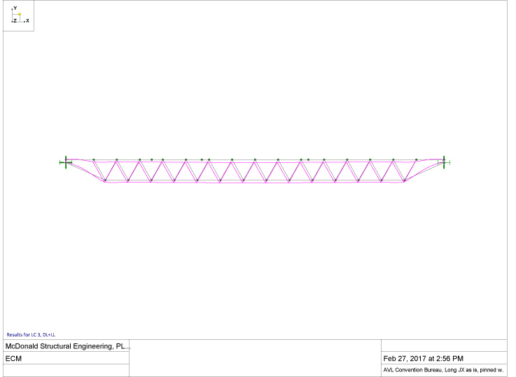
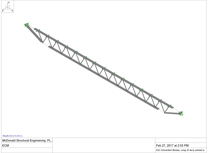
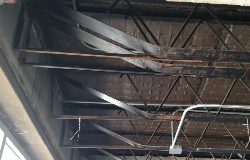
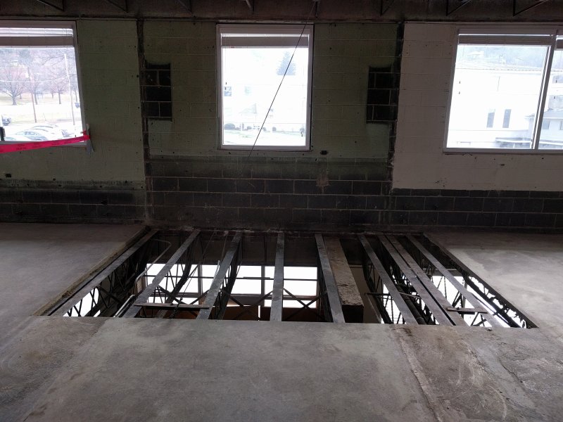
I am working on a 1952 office building (originally a school, but has been used as an office building for many years), in which there are existing open web steel joists to be shortened. The existing open web steel joists have a custom top and bottom chord in a WT-configuration. The top and bottom chords are made of the 1/8" (deep) !!! x 3 3/8" (wide) flange with a 3/8" (wide) x 3/4" (high) stem. The web is a continuous 5/8" diameter rod zigzagging and welded to the stem. These joists span over 24.5-ft, are spaced 2-ft o/c, and support a 2.5-in deep unreinforced concrete slab.
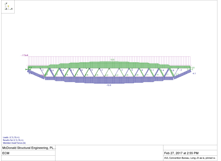
I did a RISA model, modeling the flanges as 7/32" x 3.375" plates (which has the same cross section area as the actual WT-members.) There are three rows of bridgeing, which I used for the unbraced length of top and bottom flanges, plus the web node spacing in the other direction. For allowable steel stresses I am using the then common A7 steel. For the top flange the RISA model comes up with "compressive stress fa exceeds F'e (Euler buckling)", and the bottom chord stressed at 465% of its allowable stress in its original condition. Even reducing the unbraced length of the top chord to 3" in the transverse direction (the existing slab undulates and locks in the joist from side way movement), the joist is not working.
Looking at joist performance, I did not observe signs of distress. There are areas of the slab cracked though, but without a general pattern.
I am hesitant to just modify the existing truss, even though the net-stresses are less (still over-stressed in RISA) even after shortening the joists by 7-ft. I am also hesitant removing the joists, as the existing slab is unreinforced and has a 65 year history of tension and compressive stresses within the slab based on the current joist layout. My inclination is to add new W8x18 joists side by side with the existing joists, plus adding the new joist web and bottom chord at the cut end.
Do you think this is reasonable, or excessively conservative?
Thanks Guys!
Eric McDonald, PE
McDonald Structural Engineering, PLLC
Eric McDonald, PE
McDonald Structural Engineering, PLLC

