Eng-Tips is the largest engineering community on the Internet

Intelligent Work Forums for Engineering Professionals

Modeling curved beam in femap 1

Status
Not open for further replies.

manees90

Aerospace
Apr 28, 2011
7
0
0
GB
Hi, I am trying to model a beam that has an initially curved shape. When I apply body force in direction perpendicular to the beam, it deforms unusually. Can anyone point to why it is happening and how to fix it?
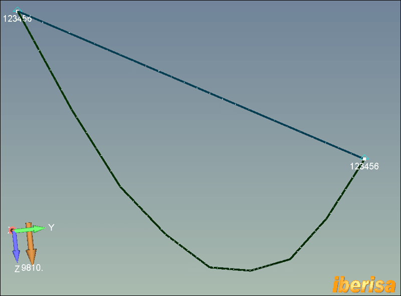
In the attached image, the white curve is the undeformed shape while the colored curve is the deformed shape. 1g body force is applied in +Z direction. As a comparison a straight beam with the same properties and loading is shown which bends in the normal way.
Many Thanks!
 
 https://files.engineering.com/getfile.aspx?folder=76f606aa-6905-4638-ad2d-a59392194b89&file=Image_(1).png
Replies continue below

Recommended for you

It is difficult to say something without model. Can you upload Femap Neutral file (File->Export->Femap neutral and select some old version like 11.0) or .dat file.
 
I think there may be something in how you created your geometry. I'd ask the help desk, or maybe Blas can help ?

"Hoffen wir mal, dass alles gut geht !"
General Paulus, Nov 1942, outside Stalingrad after the launch of Operation Uranus.
 
what happens if you model 1/2 the beam ?

"Hoffen wir mal, dass alles gut geht !"
General Paulus, Nov 1942, outside Stalingrad after the launch of Operation Uranus.
 
It appears to me that the problem is with the cross-section. So right now I have a 3.5m long beam with a 1.6mm cross-sectional diameter. Actually, it represents a pre-tensioned cable that is subjected to bending loads. (That is why I have modeled using a beam instead of a rod) When I increase the diameter to a good enough size, e.g. 25 mm the shape and deflections both start making sense. Any workaround to modeling a thin cable that is supposed to undergo much larger deformations as compared to its cross-sectional size?
 
is the problem that for the small cable the axial load dominates (like membrane loads in thin sheets) ? Maybe you need "large displacements" (even though you don't have them) ?

"Hoffen wir mal, dass alles gut geht !"
General Paulus, Nov 1942, outside Stalingrad after the launch of Operation Uranus.
 
Dear Manees90,
You have setup a BEAM model of length 3575 mm to run by a linear static analysis, but the cross section is a bar of diameter 1,6 mm (!!??): crazy!.
This is all less linear, you have a nonlinear behaviour for the geometry: you need to account for large displacements effect!!.
The beam theory has its limitations: you are trying to solve a cable-like problem, not a beam problem, and you need to activateh the nonlinrar solver. There you will see the HORIZONTAL reaction force to be many times the value of vertical reaction force, like a cable, OK?.
cable-like_fjygxp.png

Best regards,
Blas.


~~~~~~~~~~~~~~~~~~~~~~
Blas Molero Hidalgo
Ingeniero Industrial
Director

IBERISA
48004 BILBAO (SPAIN)
WEB: Blog de FEMAP & NX Nastran:
 
Thanks, @Blas Molero for your valuable response. Yes, you are totally right, and now I understand that it is a nonlinear problem. I am new to non-linear analysis field. I want to run both a modal analysis and static analysis on a structure that is being stiffened with such pre-tensioned cables. Should I define non-linearity in the material properties, or in the analysis setup? How would modal analysis be set-up up for non linear model in Femap. If you can provide some guidelines or refer me to any resource, it will be extremely helpful
Thanks again.
 
Hello!,
The nonlinearity is not for the material, but for the "geometry", this is the term we use to denominate a behaviour where large displacements exist, here the relation force vs displacements is non linear, not matter the stress state of the material that surely will be well below the yield stress, see the following image:

nonlinear-by-geometry_vryhkg.png


When you define a NON LINEAR STATIC (SOL106) analysis automatically the geometric nonlinearity is automatically activated writing PARAM,LGDISP,1 in the NASTRAN BULK DATA:

NONLINEAR-analysis_klc0ft.png


But before attenting to run a nonlinar analysis using a real life problem I suggest to run the EXAMPLE PROBLEMS you have in FEMAP in HELP > EXAMPLES to learn the procedure.

Also, for modal analysis, yes, the natural frequency depends of the loadings applied to the structure, but this is for spacial cases where the structure is very flexible, if is very stiff the effect is negligible, imaging pretensioning a guitar strings, but you need to learn how to do it with FEMAP: please visit my blog

definicion-del-problema3_vj2vgp.png


Best regards,
Blas.

~~~~~~~~~~~~~~~~~~~~~~
Blas Molero Hidalgo
Ingeniero Industrial
Director

IBERISA
48004 BILBAO (SPAIN)
WEB: Blog de FEMAP & NX Nastran:
 
Status
Not open for further replies.
Back
Top